Earth Rods Resistance Calculator
This calculator determines the earth resistance of buried rods for a single bare rod, single concrete enclosed rod to rod beds (multiple rods) either bare or enclosed in concrete. For rod beds the effect of the horizontal buried conductors is not considered, therefore the results are conservative.
The simple equations used are taken directly from or derived from Section 14.6 of the IEEE Guide for Safety in AC Substation Grounding (IEEE Std 80-2013). The limitations of the equations include they only deal with uniform soil and they are not suitable for two layer or multilayer soils for example, they also don’t deal with rods which are non-uniformly separated.
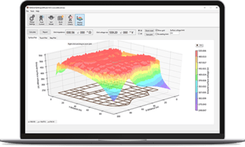
SafeGrid Earthing Software can calculate buried earth rod resistance for any size or shape earth grid with a high degree of accuracy.
Try our other 12 Free Electrical Calculators.
Earthing Rod resistance
This calculator finds the rod resistance of a singular rod or multiple rods of a grid buried in a uniform soil model. Also, it finds the resistance of the electrodes when encased in concrete.
Equations:
1. Single rod
The common formula used to calculate a single rod resistance [1] is:

Where:
ρ: the resistivity of the soil (Ω.m).
Lr: length of the rod.
d: diameter of the ground rod.
2. Single rod encased in concrete
In a high resistivity soil, it is best to add an extra layer of concrete to the rods as concrete has a lower resistivity of 30Ω.m to 200Ω.m depending on the moisture level. Therefore, it works as a low resistivity soil around the rods which gives extra protection.
We can obtain the rod resistance that is encased in concrete by using the Fagan and Lee [2] equation:

Where:
ρc: the resistivity of the concrete (Ω.m)
Dc: the diameter of the concrete encasement (m)
3. Rod bed
Schwarz [1] used the following formula to determine the resistance of a rod bed:
Where:
A: Area of the grid (m^2)
nr: number of rods placed in area A.
k1: coefficient.
Later on, Kercel [3] formulated an equation to calculate the coefficient for a rectangular grid depending on the area of the grid (length and width).
The formula for the coefficient is:

Where:
a: the length of the grid (m)
b: the width of the grid(m)
4. Rod bed of concrete encased rods
From (3) we have:

Substituting (1) in (5) we have:

For a rod encased in concrete, we substitute in (2) with in (6). Then we have:

Giving the formula of a rod bed for rods encased in concrete (Figure 1).

References:
[1] ‘IEEE Guide for Safety in AC Substation Grounding.’ IEEE Power and Energy Society. USA. 2013, p. 204
[2] Fagan, E.J. and Lee, R. H., “The use of concrete-enclosed reinforcing rods as grounding electrodes”, IEEE Transactions on Industry and General Applications, IGA-6: No. 4, Jul. 1970.
[3] Kercel, S. W., “Design of switchyard grounding systems using multiple grids” IEEE Transactions on Power Apparatus and Systems, vol. PAS-100, no. 3, pp. 1341–1350, Mar. 1981.
Free Electrical Calculators:
SafeGrid Earthing Software

Easily design safe earthing systems in compliance with Standards.
As used by:


