Call Us: 1300 093 795
Email Us: enquiry@elek.com.au

  • Login Cable Pro
Menu
  • Login Cable Pro
Electrotechnik
  • Software
    • Cable Pro Web (AU)
    • Cable Pro Web (UK)
    • Protection Coordination
    • SafeGrid Earthing
    • Cable High Voltage
    • Cable Pulling
    • Bare Conductor Ratings
    • Power Bundle
  • Resources
    • Article Categories
      • Low Voltage Design
      • Earthing Design
      • High Voltage Cable Design
      • Electrical Software
      • Arc Flash Studies
    • Tutorials
    • Free Calculators
      • Cable Sizing AS3008
      • Cable Sizing BS7671
      • Voltage Drop
      • Arc Flash
      • Earth Cable Sizing
      • Fault Loop Impedance
      • Earth Grid Resistance
      • Earth Grid Conductor Sizing
      • Earthing Rods Resistance
      • Lightning Protection Design
      • Relay Tripping Time
      • Equivalent Thermal Resistance
    • Courses
      • SafeGrid Earthing Software Course
    • Technical Publications
    • Training and Certification
  • Support
    • Support Overview
    • Help Portal
  • About
    • About Us
    • Contact Us
    • Services
    • Careers
    • Reseller & Partner Program
  • Login
    • Cable Pro Web Login
    • Training Courses Login
    • Customer Licence Portal
  • TRY FOR FREE
  • SCHEDULE A DEMO
  • TRY FOR FREE
  • SCHEDULE A DEMO
  • TRY FOR FREE
Menu
  • Software
    • Cable Pro Web (AU)
    • Cable Pro Web (UK)
    • Protection Coordination
    • SafeGrid Earthing
    • Cable High Voltage
    • Cable Pulling
    • Bare Conductor Ratings
    • Power Bundle
  • Resources
    • Article Categories
      • Low Voltage Design
      • Earthing Design
      • High Voltage Cable Design
      • Electrical Software
      • Arc Flash Studies
    • Tutorials
    • Free Calculators
      • Cable Sizing AS3008
      • Cable Sizing BS7671
      • Voltage Drop
      • Arc Flash
      • Earth Cable Sizing
      • Fault Loop Impedance
      • Earth Grid Resistance
      • Earth Grid Conductor Sizing
      • Earthing Rods Resistance
      • Lightning Protection Design
      • Relay Tripping Time
      • Equivalent Thermal Resistance
    • Courses
      • SafeGrid Earthing Software Course
    • Technical Publications
    • Training and Certification
  • Support
    • Support Overview
    • Help Portal
  • About
    • About Us
    • Contact Us
    • Services
    • Careers
    • Reseller & Partner Program
  • Login
    • Cable Pro Web Login
    • Training Courses Login
    • Customer Licence Portal
  • TRY FOR FREE
  • SCHEDULE A DEMO
  • TRY FOR FREE
  • SCHEDULE A DEMO
  • TRY FOR FREE

Home / Articles / Low Voltage Design

Voltage Rise Calculations

Standards for solar electrical projects
Solar panels on Sydney building 1 scaled - Voltage Rise Calculations

What is voltage rise?

Voltage rise occurs in solar PV systems on the AC side between the power inverters and the network connection when power flows from the inverter back into the network.

Maximum limits for voltage rise are in place to avoid excessive voltages within the consumers installation and help reduce the occurrence of overvoltage protection trips on the inverters.  

The limits set by the Standards for voltage rise are lower than for voltage drop since the power system normally operates above its nominal value and so there is less tolerance.  For example, the nominal voltage level in Australia is 230 V (-6 %, +10%) however the average (normal) system operating voltage is around 240 V.

You can calculate the voltage rise by hand or using software.

What are the voltage rise requirements?

There is an Australian Standard and there are state regulations covering the requirements and the limits for voltage rise.

The most widely-used limit in Australia is set by the AS/NZS 4777.1 –  the overall voltage rise from the point of supply to the inverter AC terminals (grid-interactive port) shall not exceed 2% of the nominal voltage at the point of supply.  Certain States in Australia (particularly NSW) also have specific requirements in their ‘Service & Installation Rules (SIR)’.

Table 1 summarises the voltage rise limits across Australia.

Table 1 – Voltage rise limits across Australia

Document Requirements Special consideration
AS/NZS 4777.1 Clause 3.3:
From the point of supply to the inverter a.c. terminals, the overall voltage rise
N/A
NSW SIR: 2019 Clause 8.6.13:
Service mains: Consumers mains: MSB <> Inverter (submains and final subcircuit):
Clause 8.6.13.1:
up to 2 % voltage rise may be permitted on any one component, if the sum of voltage rise on the remaining two components is less than or equal to 1 %.
VIC SIR: 2019 Clause 6.9.4.15:
Voltage rise from the Inverter terminals to the point of supply shall comply with requirements of AS/NZS 4777.1.
N/A
QLD QECM1: 2018
SA SIR: 2017
WA ER2: 2014
Not mentioned N/A

1 QECM: Queensland Electricity Connection Manual
2 ER: Electrical Requirements

How to calculate voltage rise

Voltage rise is not different to voltage drop calculations. Two methods, the simple and the accurate methods are discussed below. The simple method is covered in AS/NZS 3000:2018 Appendix C4.  The accurate method is covered in AS/NZS 3008.1:2017 Sections 4.4 and 4.5.

1 Simplified voltage rise calculation

The basic formula for this method is:

volt rise calcs formula 1 - Voltage Rise Calculations
Where Vd is the actual voltage drop on circuit, in volts; L is the route length of circuit, in metres; I is the circuit current, in amperes; Vc is the cable voltage drop per ampere-metre length of the circuit, in millivolts per ampere-metre. Values of Vc are tabulated in the Standard AS/NZS 3008.1. To express the resulting voltage rise in percentage with respect to circuit operating voltage:
volt rise calcs formula 2 - Voltage Rise Calculations
Where %Vd is the actual voltage drop as a fraction of the circuit-operating voltage; Vo is circuit-operating voltage, in volts. The above formula can be rewritten as:
volt rise calcs formula 3 - Voltage Rise Calculations
The values of Am per %Vd are tabulated in Table C8 in AS/NZS 3000:2018. The voltage rise in percentage term is then:
volt rise calcs formula 4 - Voltage Rise Calculations
Once the length of circuit and circuit current are given, the voltage rise can be calculated with the value of Am per %Vd. In conclusion, this method which is derived from AS/NZS 3008.1 Section 4.2 is simple but not accurate as AS/NZS 3008.1 states.

2 Accurate voltage rise calculation

In the accurate method, resistance and reactance of a selected conductor size will be firstly obtained from Table 30 – 39 in AS/NZS 3008.1:2017 with reference to the conductor operating temperature. Formulas in AS/NZS 3008.1:2017 Section 4.5 are then applied with consideration of power factor to calculate the voltage rise accurately.

Cable Pro Web software uses this accurate voltage rise calculation method.

The accurate formula to calculate the voltage rise are shown below:

  • For a single-phase system:
volt rise calcs formula 5 - Voltage Rise Calculations
  • For a three-phase system:
volt rise calcs formula 6 - Voltage Rise Calculations
volt rise calcs formulatext 1 - Voltage Rise Calculations

Power factor of load will affect the voltage rise significantly, especially for larger size conductors of which the reactance is relatively large.

When the cable size is known or anticipated, resistance Rc. and reactance Xc. will be obtained from Table 30 – 39 in AS/NZS 3008.1:2017 with reference to the conductor operating temperature since resistance is temperature dependant.

Conductor operating temperature is calculated by the following equation:

volt rise calcs formula 7 - Voltage Rise Calculations
volt rise calcs formulatext 2 - Voltage Rise Calculations

The accurate method based on the power factor of the load, the resistance and reactance of the conductor and conductor operating temperature will result in smaller cable sizes when compared with the simple method as will be demonstrated in the next section.

Example calculations - by hand and using software

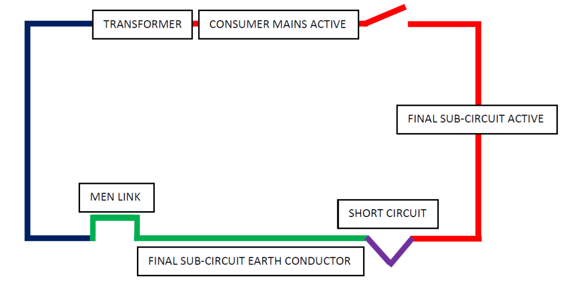
This example from Standard AS/NZS 4777.1 is for an installation with a 400 V three-phase supply, a 30 metre consumer mains length, 60 metre final sub-circuit length to the three-phase inverter and only the main switchboard for connections.

It is necessary to select suitable cable sizes for the complete installation based on requirements for current-carrying capacity and voltage rise.  For this example, two segments are considered: the consumer mains (existing installation) and the final sub-circuit to the inverter (new installation). Refer to Figure 1.

Figure 1 – Three-phase underground network connection with three-phase 30 kVA inverter system (no load)

Method 1 - Simplified voltage rise by hand calculation

  • Current-carrying capacity requirement

The required minimum current-carrying capacity for cables in the installation is determined based on the rated current of the inverters.  The current rating for the 3 phase, 30 kVA inverter equates to a current rating of 43.35 A per phase.

To satisfy this current rating, a 6 mm2 conductor size with current-carrying capacity of 45 A is selected for both consumers mains and final subcircuit. This rating is based on three single-core thermoplastic copper cables enclosed within an underground wiring enclosure, as per AS/NZS 3008.1.1:2017, Table 7, Column 24.

  • Voltage rise requirement

The overall voltage drop combining the consumer mains and the final sub-circuit to the inverter must not exceed 2 % per the AS/NZS 4777.1.  For the three phase 400 V system this equates to an overall voltage rise of 8 V. The results of conductor size based on voltage rise requirement are shown in Table 2.

Table 2 – Voltage rise and min. conductor size results – Simple method

Voltage rise Conductor size
Consumers mains 3.16 V (0.79%) 16 mm2
Final subcircuit 4.03 V (1.01%) 25 mm2

Method 2 – Accurate voltage rise calculation using software

Cable Pro Web software was used to easily determine the minimum conductor sizes while meeting the current-carrying capacity and maximum voltage rise requirements at same time.    All cables had XLPE (90 deg.C.) insulation, copper conductors and were buried below ground in separate conduits. For the consumer mains cables a voltage drop of 1/3 the overall 2 % (0.67 %) was allowed since it was a 30 m run of the overall 90 m.  For the final subcircuit a voltage rise of 2/3 the overall 2 % (1.33 %) was allowed since it was a 60 m run of the overall 90 m. Figure 2 shows the consumers mains calculation using Cable Pro Web software.
Figure 2 – Cable Pro Web screenshot of consumers mains calculation

The results of minimum conductor sizes by method 2 are shown in Table 3.

Table 3 – Voltage rise and min. conductor size results – Accurate method

Current-carrying capacity Voltage rise Conductor size
Consumers mains 101 A (> 43.35 A) 2.42 V (0.60%) 16 mm2
Final subcircuit 101 A (> 43.35 A) 4.83 V (1.21%) 16 mm2

Comparing the results for Tables 2 and 3 it is shown that the accurate voltage rise method results in a smaller cable size for the final subcircuit.

Related Articles:

elek articles lv earth fault - Voltage Rise Calculations

Understanding Earth Fault Loop Impedance

The purpose of this article is to provide a better understanding of Fault Loop Impedance, also referred to as Earth Fault Loop Impedance so that the requirements of …

Read It Now
elek articles lv voltage drop limits - Voltage Rise Calculations

Voltage Drop Limits

The voltage drop between the point of supply for the low voltage electrical installation and any point in that electrical installation must not exceed 5 % of the nominal voltage of the point of supply.

Read It Now
Cable Pro Web

Cable sizing and maximum demand software in the cloud. No installation, use on any device.

Try For Free

Print this article:

Share on print
Print
Cable Pro Web

Cable sizing, maximum demand and protection design software.

Try For Free
Watch Demo Video

As used by:

For information or to speak with our helpful advisors

GET IN TOUCH

GET IN TOUCH

Electrotechnik-Footer

Electrical Power Systems Design & Analysis Software

FOLLOW US

social-fb
social-yt
social-li

SOFTWARE

  • Cable Pro Web
  • Protection Coordination
  • SafeGrid Earthing
  • Cable High Voltage
  • Cable Pulling
  • Line Rate
  • Power Bundle
Menu
  • Cable Pro Web
  • Protection Coordination
  • SafeGrid Earthing
  • Cable High Voltage
  • Cable Pulling
  • Line Rate
  • Power Bundle

RESOURCES & SUPPORT

  • Software Tutorials
  • Technical Publications
  • Training and Certification
  • Customer Licence Portal
Menu
  • Software Tutorials
  • Technical Publications
  • Training and Certification
  • Customer Licence Portal

CONTACT US

Email:
enquiry@elek.com.au

Need Help?
Lodge a Support Ticket

Phone:
1300 093 795
International:
+61 (0)2 8231 6673

FREE TECHNICAL NEWS

© 2022 All Rights Reserved    Privacy Policy Quality Policy Terms of Use

SafeGrid Earthing 14 day Free Trial

Fill out your details below to begin your trial. Once your information has been submitted you’ll be able to download the software.

  • Fill out your details below to begin your trial. Once your information has been submitted you'll be able to download the software.

  • This field is for validation purposes and should be left unchanged.

CLOSE

Schedule a Demo for Cable High Voltage

Look No Further. Get Started Today

  • This field is for validation purposes and should be left unchanged.
Schedule a Demo for SafeGrid Earthing

Look No Further. Get Started Today

  • This field is for validation purposes and should be left unchanged.
SafeGrid Earthing Free Trial
  • Fill out your details below to begin your trial. Once your information has been submitted you'll be able to download the software.

  • This field is for validation purposes and should be left unchanged.
Cable High Voltage Free Trial
  • Fill out your details below to begin your trial. Once your information has been submitted you'll be able to download the software.

  • This field is for validation purposes and should be left unchanged.
Cable High Voltage 14 day Free Trial

Fill out your details below to begin your trial. Once your information has been submitted you’ll be able to download the software.

  • Fill out your details below to begin your trial. Once your information has been submitted you'll be able to download the software.

  • This field is for validation purposes and should be left unchanged.

CLOSE

  • We strive for 100% customer satisfaction. If we fell short, please tell us more so we can address your concerns.

  • This field is for validation purposes and should be left unchanged.

If you do not wish to address your concerns here and prefer to post a review, click here.

Cable Pro (PC) Free Trial

Fill out your details below to begin your trial. Once your information has been submitted you’ll be able to download the software.

  • Fill out your details below to begin your trial. Once your information has been submitted you'll be able to download the software.

  • This field is for validation purposes and should be left unchanged.

CLOSE