Call Us: 1300 093 795
Email Us: enquiry@elek.com.au

  • Login Cable Pro
Menu
  • Login Cable Pro
Electrotechnik
  • Software
    • Cable Pro Web (AU)
    • Cable Pro Web (UK)
    • Protection Coordination
    • SafeGrid Earthing
    • Cable High Voltage
    • Cable Pulling
    • Bare Conductor Ratings
    • Power Bundle
  • Resources
    • Article Categories
      • Low Voltage Design
      • Earthing Design
      • High Voltage Cable Design
      • Electrical Software
      • Arc Flash Studies
    • Tutorials
    • Free Calculators
      • Cable Sizing AS3008
      • Cable Sizing BS7671
      • Voltage Drop
      • Arc Flash
      • Earth Cable Sizing
      • Fault Loop Impedance
      • Earth Grid Resistance
      • Earth Grid Conductor Sizing
      • Earthing Rods Resistance
      • Lightning Protection Design
      • Relay Tripping Time
      • Equivalent Thermal Resistance
    • Courses
      • SafeGrid Earthing Software Course
    • Technical Publications
    • Training and Certification
  • Support
    • Support Overview
    • Help Portal
  • About
    • About Us
    • Contact Us
    • Careers
    • Reseller & Partner Program
  • Login
    • Cable Pro Web Login
    • Training Courses Login
    • Customer Licence Portal
  • TRY FOR FREE
  • SCHEDULE A DEMO
  • TRY FOR FREE
  • SCHEDULE A DEMO
  • TRY FOR FREE
Menu
  • Software
    • Cable Pro Web (AU)
    • Cable Pro Web (UK)
    • Protection Coordination
    • SafeGrid Earthing
    • Cable High Voltage
    • Cable Pulling
    • Bare Conductor Ratings
    • Power Bundle
  • Resources
    • Article Categories
      • Low Voltage Design
      • Earthing Design
      • High Voltage Cable Design
      • Electrical Software
      • Arc Flash Studies
    • Tutorials
    • Free Calculators
      • Cable Sizing AS3008
      • Cable Sizing BS7671
      • Voltage Drop
      • Arc Flash
      • Earth Cable Sizing
      • Fault Loop Impedance
      • Earth Grid Resistance
      • Earth Grid Conductor Sizing
      • Earthing Rods Resistance
      • Lightning Protection Design
      • Relay Tripping Time
      • Equivalent Thermal Resistance
    • Courses
      • SafeGrid Earthing Software Course
    • Technical Publications
    • Training and Certification
  • Support
    • Support Overview
    • Help Portal
  • About
    • About Us
    • Contact Us
    • Careers
    • Reseller & Partner Program
  • Login
    • Cable Pro Web Login
    • Training Courses Login
    • Customer Licence Portal
  • TRY FOR FREE
  • SCHEDULE A DEMO
  • TRY FOR FREE
  • SCHEDULE A DEMO
  • TRY FOR FREE

Home / Articles / Low Voltage Design

Voltage Drop Calculation Method with Examples

Accurate voltage drop, balanced or unbalanced with calculations explained

Voltage drop equation

The voltage drop in a circuit represents the difference between the voltage from the supply end and the voltage at the load end. When determining the maximum voltage drop, an equation can be applied under the assumption that the power factor of the cable is equal to that of the load.

This equation can be expressed as:

\(V_d = I \cdot Z_c\)     (Eq. 1)

Where:

    • Vd is voltage drop in cable, in volts
    • I is current flowing through cable in amperes
    • Zc is impedance of conductors in ohms whereby,= √((Rc2+ Xc2))

Rc represents cable resistance which is a function of conductor material, size and operating temperature. Xc represents cable reactance being a function of shape and phase spacing.

Note for DC voltage drop calculations the value for reactance Xc is zero.

Voltage drop based on power factor

In a case where the supply and load voltages differ in terms of phase angle, another set of equations are to be used to compensate for this change. When the current is leading the voltage, the supply voltage ends up being smaller than the load voltage. The voltage drop IZc is identical in all power factor cases but is different in terms of phase angle except for when the cable and load power factors are equal which shows the voltage drop Vd is a maximum of IZc. The following equations apply for lagging power factors.

For a single-phase system

\(V_{d1\phi} = IL[2(R_c cos \theta + X_c sin \theta)]\)    (Eq. 2)

For a balanced three-phase system

\(V_{d3\phi} = IL[\sqrt{3}(R_c cos \theta + X_c sin \theta)]\)    (Eq. 3)

Resistance and cable operating temperature

The resistance of a cable is dependent on temperature and the standard provides tables of resistance for a particular operating temperature.

In a situation where the cable operating temperature is less than the maximum figure provided by the Standard tables, the conductor temperature can be estimated using the following equation:


\(\theta_{0} = (\theta_{R} – \theta_{A})(\frac{I_0}{I_R})^2 + \theta_{A}\)    (Eq. 4)


Where: 

  • I0 = operating current, in amperes
  • IR = rated current provided in the current rating tables (from Tables 4-21 in AS/NZS 3008.1)
  • 00= operating temperature of cable when carrying , in degrees Celsius
  • 0A= ambient air or soil temperature, in degrees Celsius.

Once cable operating temperature is calculated then the cable resistance can be selected. In the case of AS/NZS 3008.1 the Tables 34-50 provides resistance values for the following operating temperatures 45oC, 60oC, 75oC, 80oC, 90oC, 110oC and the calculated operating temperature is then raised (more conservative) to the nearest temperature.

Voltage drop for unbalanced multiphase circuits

In an unbalanced system, current will be flowing through the neutral conductor as illustrated by the phasor diagram in Figure 1:

processed 6633f313 eb09 4bcd af31 9b3b31664d6b m4i0GfUZ - Voltage Drop Calculation Method with Examples
Figure 1: Phasor diagram for an unbalanced system

There are two ways of dealing with voltage drop in these cases. A conservative solution is to assume a balanced three-phase load and to perform calculations using the current flowing in the heaviest loaded phase. However, where the currents in each phase can be shown to be of different magnitudes for consistent periods then voltage drop can be calculated on a single-phase basis by summing the voltage drop in the heaviest loaded phase plus the voltage drop in the neutral as shown by the equation below.


\(V_d = I_A L_A Z_{cA} + I_N L_N Z_{cN}\)    (Eq. 5)


In the next section, we will provide an example voltage drop calculation.

Example voltage drop calculation

Single core cables with copper conductors and XLPE insulated are connected to a 3 phase 400 V supply. The installation is buried direct in the ground (reference ambient temperature is 25oC) over 120 m length of run. The load current is 240 A at power factor of 0.9.

What is the 3-phase voltage drop?


Step 1: Determine cable operating temperature
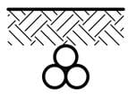
The minimum conductor size from current-rating Table 8, column 22 is 70 mm2 which has a maximum current rating of 277 A.
processed 0fd22572 7716 4175 bde3 678c06e60a7d 1gxuILjI - Voltage Drop Calculation Method with Examples

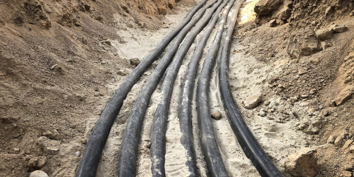
Figure 2: Illustration of the cable buried directly in the ground.

The normal use operating temperature for XLPE insulated cables is 90˚C. Using Equation 4 for cable operating temperature:

\(\theta_0 = (90^{\circ} – 25^{\circ})(\frac{240}{277})^2 + 25^{\circ}\)

Step 2: Determine cable resistance based on cable operating temperature

Using Table 34 (refer to Appendix 1 below) we can find the AC resistance of the cable matching with the conductor size and at the conductor temperature nearest to the cable operating temperature calculated in Step 1. Since we calculated a temperature of 73.8°, we should round up the temperature and assume that 75° is the most accurate temperature to use.

Per Table 34, the resistance of a cable with a 70 mm2 copper conductor and an operating temperature of 75° is 0.327 Ω/km, or 0.000327 Ω/m.

Step 3: Determine cable reactance

The reactance for single core cables depends on the cable type and separation of the cables.

Using Table 30 (refer to Appendix 2 below) we can find the reactance at 50 Hz.


Our cables are in a trefoil arrangement, therefore from Column 3 the cable reactance is 0.0893 Ω/km, or 0.0000893 Ω/m.

Step 4: Calculate voltage drop based on power factor and cable operating temperature

We will use Equation 3 to calculate the 3-phase voltage drop. For this we need the phase angle of the load based the given load power factor as follows:

\(\theta = cos^{-1}(0.9)\)

\(\theta = 25.84193276^{\circ} = 0.4510268 \; rads\)

\(sin\theta = 0.43588989\)

Now, we have all parameters needed to calculate the three-phase voltage drop:

\(V_{d3\phi} = 250 \cdot 120[\sqrt{3}(0.000327 \cdot 0.9 + 0.0000893 \cdot 0.43588989)]\)

\(V_{d3\phi} = 17.315 \; V\)

The voltage drop as a percentage of the supply voltage is 17.315 / 400 V, or 4.33%.


“Cable Pro Web software performs accurate voltage drop calculations. Try for Free.”

Appendices

Appendix 1 – Table 34 with relevant value highlighted in red

processed 6cc4e453 188b 4b25 aea5 2a03877a3f03 EOEkUbgt - Voltage Drop Calculation Method with Examples

Appendix 2 – Table 30 with relevant value highlighted in red

processed 5f519956 9564 484f 8e11 98880fa95075 vaa3zRKp - Voltage Drop Calculation Method with Examples

Try the free Voltage Drop Calculator for accurate voltage drop calculations.

Related Articles:

elek articles lv earth fault - Voltage Drop Calculation Method with Examples

Understanding Earth
Fault Loop Impedance

The purpose of this article is to provide a better understanding of Fault Loop Impedance, also referred to as Earth Fault Loop Impedance so that the requirements of …

Read It Now
elek articles lv max demand tables - Voltage Drop Calculation Method with Examples

Maximum Demand
Tables

Under normal operating conditions not all the individual electrical equipment of an installation will operate at full load and simultaneously. Therefore the total circuit current is estimated using …

Read It Now
Cable Pro Web

Cable sizing and maximum demand software in the cloud. No installation, use on any device.

Try For Free

Print this article:

Share on print
Print
Cable Pro Web

Cable sizing, maximum demand and protection design software.

Try For Free
Watch Demo Video

As used by:

For information or to speak with our helpful advisors

GET IN TOUCH

GET IN TOUCH

Electrotechnik-Footer

Electrical Power Systems Design & Analysis Software

FOLLOW US

social-fb
social-yt
social-li

SOFTWARE

  • Cable Pro Web
  • Protection Coordination
  • SafeGrid Earthing
  • Cable High Voltage
  • Cable Pulling
  • Line Rate
  • Power Bundle
Menu
  • Cable Pro Web
  • Protection Coordination
  • SafeGrid Earthing
  • Cable High Voltage
  • Cable Pulling
  • Line Rate
  • Power Bundle

RESOURCES & SUPPORT

  • Software Tutorials
  • Technical Publications
  • Training and Certification
  • Customer Licence Portal
Menu
  • Software Tutorials
  • Technical Publications
  • Training and Certification
  • Customer Licence Portal

CONTACT US

Email:
enquiry@elek.com.au

Need Help?
Lodge a Support Ticket

Phone:
1300 093 795
International:
+61 (0)2 8231 6673

FREE TECHNICAL NEWS

© 2022 All Rights Reserved    Privacy Policy Quality Policy Terms of Use

Schedule a Demo for Cable High Voltage

Look No Further. Get Started Today

  • This field is for validation purposes and should be left unchanged.
Schedule a Demo for SafeGrid Earthing

Look No Further. Get Started Today

  • This field is for validation purposes and should be left unchanged.
SafeGrid Earthing Free Trial
  • Fill out your details below to begin your trial. Once your information has been submitted you'll be able to download the software.

  • This field is for validation purposes and should be left unchanged.
Cable High Voltage Free Trial
  • Fill out your details below to begin your trial. Once your information has been submitted you'll be able to download the software.

  • This field is for validation purposes and should be left unchanged.
SafeGrid Earthing 14 day Free Trial

Fill out your details below to begin your trial. Once your information has been submitted you’ll be able to download the software.

  • Fill out your details below to begin your trial. Once your information has been submitted you'll be able to download the software.

  • This field is for validation purposes and should be left unchanged.

CLOSE

Cable High Voltage 14 day Free Trial

Fill out your details below to begin your trial. Once your information has been submitted you’ll be able to download the software.

  • Fill out your details below to begin your trial. Once your information has been submitted you'll be able to download the software.

  • This field is for validation purposes and should be left unchanged.

CLOSE

  • We strive for 100% customer satisfaction. If we fell short, please tell us more so we can address your concerns.

  • This field is for validation purposes and should be left unchanged.

If you do not wish to address your concerns here and prefer to post a review, click here.

Cable Pro (PC) Free Trial

Fill out your details below to begin your trial. Once your information has been submitted you’ll be able to download the software.

  • Fill out your details below to begin your trial. Once your information has been submitted you'll be able to download the software.

  • This field is for validation purposes and should be left unchanged.

CLOSE