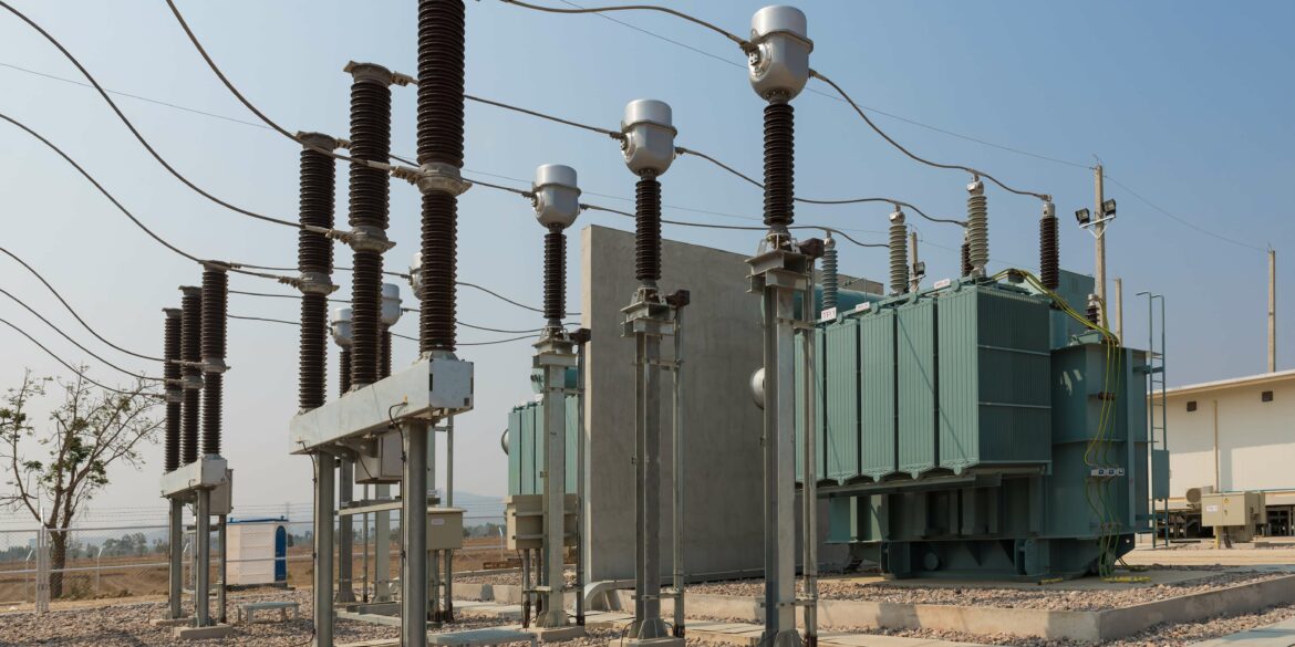
Call Us: 1300 093 795
Email Us: enquiry@elek.com.au

  • Login Cable Pro
Menu
  • Login Cable Pro
Electrotechnik
  • Software
    • Cable Pro Web (AU)
    • Cable Pro Web (UK)
    • Protection Coordination
    • SafeGrid Earthing
    • Cable High Voltage
    • Cable Pulling
    • Bare Conductor Ratings
    • Power Bundle
  • Resources
    • Article Categories
      • Low Voltage Design
      • Earthing Design
      • High Voltage Cable Design
      • Electrical Software
      • Arc Flash Studies
    • Tutorials
    • Free Calculators
      • Cable Sizing AS3008
      • Cable Sizing BS7671
      • Voltage Drop
      • Arc Flash
      • Earth Cable Sizing
      • Fault Loop Impedance
      • Earth Grid Resistance
      • Earth Grid Conductor Sizing
      • Earthing Rods Resistance
      • Lightning Protection Design
      • Relay Tripping Time
      • Equivalent Thermal Resistance
    • Courses
      • SafeGrid Earthing Software Course
    • Technical Publications
    • Training and Certification
  • Support
    • Support Overview
    • Help Portal
  • About
    • About Us
    • Contact Us
    • Careers
    • Reseller & Partner Program
  • Login
    • Cable Pro Web Login
    • Training Courses Login
    • Customer Licence Portal
  • TRY FOR FREE
  • SCHEDULE A DEMO
  • TRY FOR FREE
  • SCHEDULE A DEMO
  • TRY FOR FREE
Menu
  • Software
    • Cable Pro Web (AU)
    • Cable Pro Web (UK)
    • Protection Coordination
    • SafeGrid Earthing
    • Cable High Voltage
    • Cable Pulling
    • Bare Conductor Ratings
    • Power Bundle
  • Resources
    • Article Categories
      • Low Voltage Design
      • Earthing Design
      • High Voltage Cable Design
      • Electrical Software
      • Arc Flash Studies
    • Tutorials
    • Free Calculators
      • Cable Sizing AS3008
      • Cable Sizing BS7671
      • Voltage Drop
      • Arc Flash
      • Earth Cable Sizing
      • Fault Loop Impedance
      • Earth Grid Resistance
      • Earth Grid Conductor Sizing
      • Earthing Rods Resistance
      • Lightning Protection Design
      • Relay Tripping Time
      • Equivalent Thermal Resistance
    • Courses
      • SafeGrid Earthing Software Course
    • Technical Publications
    • Training and Certification
  • Support
    • Support Overview
    • Help Portal
  • About
    • About Us
    • Contact Us
    • Careers
    • Reseller & Partner Program
  • Login
    • Cable Pro Web Login
    • Training Courses Login
    • Customer Licence Portal
  • TRY FOR FREE
  • SCHEDULE A DEMO
  • TRY FOR FREE
  • SCHEDULE A DEMO
  • TRY FOR FREE

Home / Articles / Earthing Design

Use of Rods to Improve Grid Safety

Use vertical rods to reduce grid resistance and voltages to improve the safety of earthing systems

Overview

This engineering guide relates to the use of SafeGrid earthing design and analysis software to IEEE Std 80 and IEC 60479.
The principles contained within this Engineering Guide apply generally to the topic of electrical earthing and grounding.

Summary of recommendations

  1. When the soil model is high-on-low resistivity use rods which penetrate into the lower layer to reduce grid resistance.
  2. Use rods at the corners of the grids where step and touch potentials are largest.
  3. It is not economical to use rods where the bottom layer soil resistivity is higher than the top layer (low-on-high).
Figure 1 Summary of recommendations

Earthing systems

An earthing system should be installed in a manner that will limit the effect of ground potential gradients to such voltage and current levels that will not endanger the safety of people or equipment under normal and under fault conditions. 
 
Typically the way this is achieved is by using a system of ground electrodes which form a grid a horizontally buried conductors, supplemented by a number of vertical ground rods connected to the grid.
This concept represents the prevailing practice used around the world.
 

Grid conductors and rods

In substations a single electrode is, by itself, inadequate in providing a safe grounding system.
In turn, when several electrodes, such as ground rods, are connected to each other and to all equipment neutrals, frames, and structures that are to be grounded, the result is essentially a grid arrangement of ground electrodes, regardless of the original objective. 
 
If the connecting links happen to be buried in a soil having good conductivity, this network alone may represent an excellent grounding system.
Partly for this reason, some utilities depend on the use of a grid alone.  However, under certain circumstances ground rods are of particular value.
 

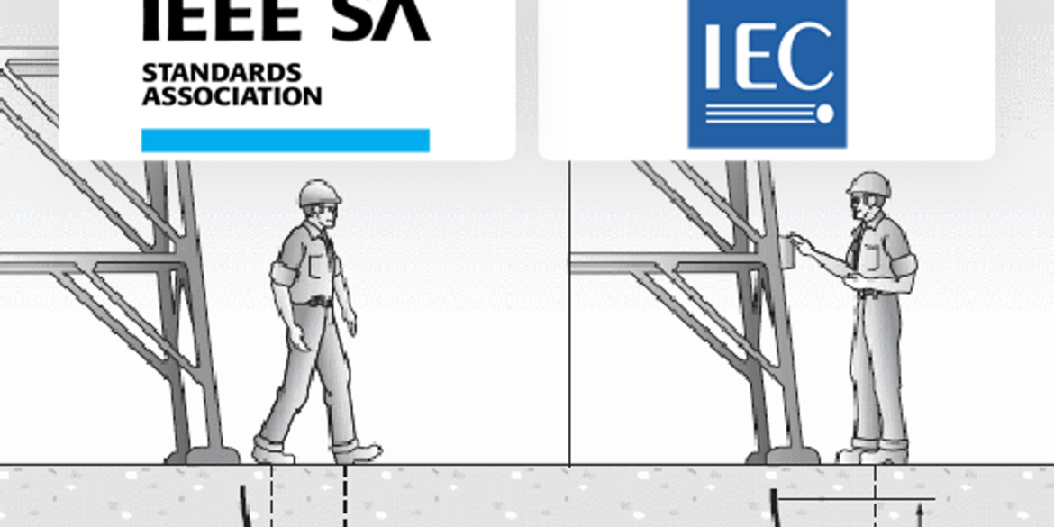
Safe earthing systems

Under the following condition(s) it is seldom possible to install a grid with resistance so low as to assure that the rise of a ground potential will not generate surface gradients unsafe for human contact:
  1. If the magnitude of the fault current to be dissipated to the earth is high.
  2. The resistivity of the soil is high.
  3. The area over which the earth grid can be installed is small.

Use of earthing rods

Under any of the (common) condition(s) mentioned in Section 3 the hazard can be eliminated only by control of local potentials throughout the entire area. 
A system that combines a horizontal grid and a number of vertical ground rods penetrating lower soils has the following advantages:
  1.  While horizontal (grid) conductors are most effective in reducing the danger of high step and touch voltages on the earth’s surface, provided that the grid is installed in a shallow depth, sufficiently long ground rods will stabilize the performance of such a combined system.
  2. Freezing or drying of upper soil layers could vary the soil resistivity with seasons, while the resistivity of lower soil layers remains nearly constant.
  3. Rods penetrating the lower resistivity soil are far more effective in dissipating fault currents whenever a two-layer or multilayer soil is encountered and the upper soil layer has higher resistivity than the lower layers.
  4. If the rods are installed predominately along the grid perimeter in high-on-low or uniform soil conditions, the rods will considerably reduce the steep increase of the surface gradient near the peripheral meshes.

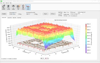
SafeGrid Example – Use of earthing rods to improve safety

Earthing rods can offer a cost effective way of reducing grid resistance and greatly improving the safety of an earthing system.  The following is a design example using the SafeGrid Earthing Software to demonstrate these principles.
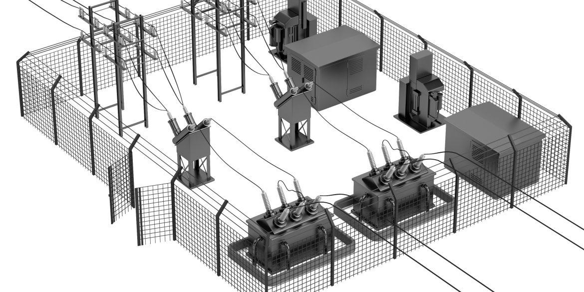
Earth grid model

A simple earthing grid was built using the SafeGrid grid editor.

  • More complex grids may be imported as a CAD (DXF) file.
  • High on low soil resistivity model.
Table 1 Earthing System Model Built Using SafeGrid
Figure 2. SafeGrid – Build Grid editor

Results

Figure 3. Surface potential plot in 3D – With earthing rods installed at corners (left) maximum = 3304 V; Without earthing rods (right) maximum = 6809 V.
Figure 4. Touch potential plot in 3D – With earthing rods installed at corners (left) maximum = 1527 V; Without earthing rods (right) maximum = 5171 V.
Figure 5. Step potential plot in 3D – With earthing rods installed at corners (left) maximum = 598 V; Without earthing rods (right) maximum = 1858 V.

Without earthing rods

The following results were obtained from the simulations for the earthing system consisting only of horizontally buried conductors without earthing rods.

Table 2 Grid Properties Without Earthing Rods - Use of Rods to Improve Grid Safety

Earth rods installed at grid corners

The following results were obtained from the simulations for the earthing system consisting of both horizontally buried conductors and four (4) 10 m long earth rods installed at the corners.

Table 3 Grid Properties with Earth Rods Installed at Grid Corners - Use of Rods to Improve Grid Safety

Conclusions

From the simulations using SafeGrid software the following conclusions can be made.
The use of earthing rods at the corners of the grid to penetrate into the lower resistivity soil layer:

  • Significantly reduces the grid resistance.
  • Fault current is much more effectively dissipated away from the surface of the earth reducing surface potentials.
  • Maximum step and touch potentials are significantly reduced.

Related Articles:

elek article header ed fundamentals sm - Use of Rods to Improve Grid Safety

Fundamentals of
Earthing Design

This tutorial introduces key concepts used in the design of substation earthing/grounding systems. Important terminology is discussed including Grid Potential Rise, touch and step voltages and current distribution.

Read It Now
elek articles hv power cables - Use of Rods to Improve Grid Safety

High Voltage Power Cable
Current Ratings

The current rating of cables is affected by the installation conditions and the cable design and materials. In this report a parametric study of the factors which affect current ratings is presented.

Read It Now

SafeGrid Earthing Software

Easily design safe earthing systems in compliance with Standards.

Try For Free

Print this article:

Share on print
Print

SafeGrid Earthing Software

SafeGrid Earthing Software

Easily design safe earthing systems in compliance with Standards.

Try For Free

As used by:

For information or to speak with our helpful advisors

GET IN TOUCH

GET IN TOUCH

Electrotechnik-Footer

Electrical Power Systems Design & Analysis Software

FOLLOW US

social-fb
social-yt
social-li

SOFTWARE

  • Cable Pro Web
  • Protection Coordination
  • SafeGrid Earthing
  • Cable High Voltage
  • Cable Pulling
  • Line Rate
  • Power Bundle
Menu
  • Cable Pro Web
  • Protection Coordination
  • SafeGrid Earthing
  • Cable High Voltage
  • Cable Pulling
  • Line Rate
  • Power Bundle

RESOURCES & SUPPORT

  • Software Tutorials
  • Technical Publications
  • Training and Certification
  • Customer Licence Portal
Menu
  • Software Tutorials
  • Technical Publications
  • Training and Certification
  • Customer Licence Portal

CONTACT US

Email:
enquiry@elek.com.au

Need Help?
Lodge a Support Ticket

Phone:
1300 093 795
International:
+61 (0)2 8231 6673

FREE TECHNICAL NEWS

© 2022 All Rights Reserved    Privacy Policy Quality Policy Terms of Use

Schedule a Demo for Cable High Voltage

Look No Further. Get Started Today

  • This field is for validation purposes and should be left unchanged.
Schedule a Demo for SafeGrid Earthing

Look No Further. Get Started Today

  • This field is for validation purposes and should be left unchanged.
SafeGrid Earthing Free Trial
  • Fill out your details below to begin your trial. Once your information has been submitted you'll be able to download the software.

  • This field is for validation purposes and should be left unchanged.
Cable High Voltage Free Trial
  • Fill out your details below to begin your trial. Once your information has been submitted you'll be able to download the software.

  • This field is for validation purposes and should be left unchanged.
SafeGrid Earthing 14 day Free Trial

Fill out your details below to begin your trial. Once your information has been submitted you’ll be able to download the software.

  • Fill out your details below to begin your trial. Once your information has been submitted you'll be able to download the software.

  • This field is for validation purposes and should be left unchanged.

CLOSE

Cable High Voltage 14 day Free Trial

Fill out your details below to begin your trial. Once your information has been submitted you’ll be able to download the software.

  • Fill out your details below to begin your trial. Once your information has been submitted you'll be able to download the software.

  • This field is for validation purposes and should be left unchanged.

CLOSE

  • We strive for 100% customer satisfaction. If we fell short, please tell us more so we can address your concerns.

  • This field is for validation purposes and should be left unchanged.

If you do not wish to address your concerns here and prefer to post a review, click here.

Cable Pro (PC) Free Trial

Fill out your details below to begin your trial. Once your information has been submitted you’ll be able to download the software.

  • Fill out your details below to begin your trial. Once your information has been submitted you'll be able to download the software.

  • This field is for validation purposes and should be left unchanged.

CLOSE