Call Us: 1300 093 795
Email Us: enquiry@elek.com.au

  • Login Cable Pro
Menu
  • Login Cable Pro
Electrotechnik
  • Software
    • Cable Pro Web (AU)
    • Cable Pro Web (UK)
    • Protection Coordination
    • SafeGrid Earthing
    • Cable High Voltage
    • Cable Pulling
    • Bare Conductor Ratings
    • Power Bundle
  • Resources
    • Article Categories
      • Low Voltage Design
      • Earthing Design
      • High Voltage Cable Design
      • Electrical Software
      • Arc Flash Studies
    • Tutorials
    • Free Calculators
      • Cable Sizing AS3008
      • Cable Sizing BS7671
      • Voltage Drop
      • Arc Flash
      • Earth Cable Sizing
      • Fault Loop Impedance
      • Earth Grid Resistance
      • Earth Grid Conductor Sizing
      • Earthing Rods Resistance
      • Lightning Protection Design
      • Relay Tripping Time
      • Equivalent Thermal Resistance
    • Courses
      • SafeGrid Earthing Software Course
    • Technical Publications
    • Training and Certification
  • Support
    • Support Overview
    • Help Portal
  • About
    • About Us
    • Contact Us
    • Careers
    • Reseller & Partner Program
  • Login
    • Cable Pro Web Login
    • Training Courses Login
    • Customer Licence Portal
  • TRY FOR FREE
  • SCHEDULE A DEMO
  • TRY FOR FREE
  • SCHEDULE A DEMO
  • TRY FOR FREE
Menu
  • Software
    • Cable Pro Web (AU)
    • Cable Pro Web (UK)
    • Protection Coordination
    • SafeGrid Earthing
    • Cable High Voltage
    • Cable Pulling
    • Bare Conductor Ratings
    • Power Bundle
  • Resources
    • Article Categories
      • Low Voltage Design
      • Earthing Design
      • High Voltage Cable Design
      • Electrical Software
      • Arc Flash Studies
    • Tutorials
    • Free Calculators
      • Cable Sizing AS3008
      • Cable Sizing BS7671
      • Voltage Drop
      • Arc Flash
      • Earth Cable Sizing
      • Fault Loop Impedance
      • Earth Grid Resistance
      • Earth Grid Conductor Sizing
      • Earthing Rods Resistance
      • Lightning Protection Design
      • Relay Tripping Time
      • Equivalent Thermal Resistance
    • Courses
      • SafeGrid Earthing Software Course
    • Technical Publications
    • Training and Certification
  • Support
    • Support Overview
    • Help Portal
  • About
    • About Us
    • Contact Us
    • Careers
    • Reseller & Partner Program
  • Login
    • Cable Pro Web Login
    • Training Courses Login
    • Customer Licence Portal
  • TRY FOR FREE
  • SCHEDULE A DEMO
  • TRY FOR FREE
  • SCHEDULE A DEMO
  • TRY FOR FREE

Home / Articles / Earthing Design

Resistance of Earthing Rods and Rod Beds

Equations for calculating earthing rod resistance validated with software
Copper earthing grid conductors buried ELEK.com .au 1 scaled - Resistance of Earthing Rods and Rod Beds

How earthing rods improve safety

Earthing rods are bare metal stakes driven vertically into the ground installed as standalone or in groups as part of an earthing system. Earthing rods may improve safety by reducing earthing grid resistance and reducing touch voltages when driven into low resistivity soil layers.

 Our article on the Fundamentals of Earthing Design explains more.

How far apart to separate earthing rods

For larger earthing systems multiple rods may be connected in the form of rod beds. The individual rods of rod beds should not be installed too close to one another due to the proximity effect which reduces their efficiency. Figure 1 shows how the fields of rods affects other rods while they are dissipating current into the ground during a fault.

The general rule of thumb is earth rods should be separated by at least their driven length.

Figure 1 - Proximity effect between two adjacent earth rods

Should earthing rods be encased in concrete?

IEEE Std. 80 [ref. 1] states that encasing rods in concrete may be effective at improving the performance of buried rods. Our article on Concrete-encased Earthing Rods explains more.

Calculating earthing rod resistance

Equations for calculating resistance of individual rods, groups of bare rods and rods encased in concrete are given below. There is also a free Earth Rods Resistance Calculator.

Example calculations are given below and the results are validated with SafeGrid Earthing Software.

Single earthing rod equation

The common formula used to calculate a single rod resistance [1] is:

11 - Resistance of Earthing Rods and Rod Beds

Where:

ρ:the resistivity of the soil (Ω.m)
Lr:length of the rod
d: diameter of the ground rod.

Rods bed equation

The simple equation used to calculate the rods bed resistance is given by Schwarz [ref. 1] as:

2 6 - Resistance of Earthing Rods and Rod Beds

Where:

ρ: Soil resistivity (Ω.m)
nr: Number of rods
Lr: Length of rod (m)
d: diameter of the rod (mm)
A: Grid area (m2)
K1: coefficients

The coefficient K1 formula was given by Kercel [ref. 2] as:

3 5 - Resistance of Earthing Rods and Rod Beds

Where a is the length of the grid and b is the width of the grid.

Rods bed encased in concrete equation

To reduce the soil resistivity around the rod (thus making it more effective) a low resistivity layer is added around it to increase its effectiveness while lowering the cost of materials. With the inclusion of concrete in equation (1), we get the following equation:
eq4 - Resistance of Earthing Rods and Rod Beds
Equation 4 - Resistance of Earthing Rods and Rod Beds

Where:
ρc: the resistivity of concrete (Ω.m)
Dc: Diameter of the concrete shell (mm)

Example hand calculations and software validation

Example 1 – Rods bed resistance

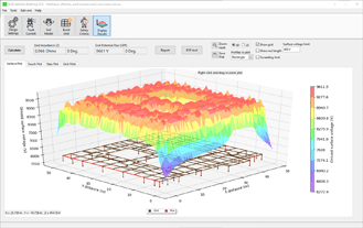
In this example we calculated the resistance of a 20 m by 10 m meshed grid shown Figure 2 which had 15 rods which are 5 m long buried at 0.5 m and were each separated by 5 m. The soil model is 100 Ω.m uniform.

Note that Equation 2 does not consider the effects of the horizontal connected conductors, which is a drawback of the simple equation approach. Therefore, in the SafeGrid software model the horizontal conductors connecting the tops of the rods together were insulated.

For the rod bed in Figure 2, Equation 2 gives a resistance of 3.19 Ω. SafeGrid software calculates 2.851 Ω for the same rod bed arrangement which is 10.6 % lower.

Figure 2. Software model of rods bed with insulated horizontal conductors
Figure 3. Software results for rod bed

To examine the proximity effects, we varied the spacing between the 5 m rods from 1m (separation factor = 0.2) up to 10 m (separation factor = 2) and calculated resistance.

Figure 4 shows that the simple rod bed resistance equation captures the proximity effect as confirmed by the SafeGrid software model results. The optimal separation between rods is when the separation distance is equal to the rod length.

Figure 4. Rod bed resistances of bare rods

Example 2 – Concrete-encased rod bed resistance

In this example the grid is the same as in Example 1 except the rods are encased in concrete with a shell diameter of 200 mm. and the concrete has resistivity of 30 Ω.m which is lower than the native soil resistivity of 100 Ω.m uniform.

For the rod bed in Figure 5, Equation 4 gives a resistance of 2.96 Ω which is lower than the result in Example 1 without concrete encasing of rods.

SafeGrid software calculates the resistance for the concrete-encased rod bed to be 2.545 Ω.

Figure 5. Software model of concrete-encased rods bed with insulated horizontal conductors
Figure 6. Software results for concrete-encased rod bed

To examine the proximity effects, we varied the spacing between the 5 m rods from 1m (separation factor = 0.2) up to 10 m (separation factor = 2) and calculated resistance.

Figure 7 shows how rod bed resistance varies for concrete-encased grid using the simple equation and using SafeGrid software. Once again, the plot confirms that optimal separation between rods is when the separation distance is equal to the rod length.

Figure 7. Rod bed resistances of concrete-encased rods

Recommendations

The simple equations from IEEE Std. 80 [ref. 1] for rod resistance and rod bend resistance have been extended to include the effects of concrete-encasing of the rods. The simple equations appear to capture the proximity effect for rods reasonably. 

The significant limitations of using the simple equations includes:

  • They can only model simple rod arrays with equal separations.
  • They cannot model the horizontal interconnecting conductors.
  • They are limited to only uniform soil models.

Most soils have a multilayer soil resistivity structure. Importantly, rods should in general be used when the bottom layer resistivity is lower than the top layers and the rods should be sufficiently long to penetrate the low resistivity layers.

The significant advantages to using software to model earthing systems includes:

  • Software can model arbitrary earthing arrangements for multi-layered soils resistivity structures.
  • Software results are more accurate resulting in higher degrees of safety and cost savings due to more economical earthing system installations.

References:

[1] ‘IEEE Guide for Safety in AC Substation Grounding.’ IEEE Std. 80-2013.
[2] Kercel, S. W., “Design of switchyard grounding systems using multiple grids” IEEE Transactions on Power Apparatus and Systems, vol. PAS-100, no. 3, pp. 1341–1350, Mar. 1981.

Related Articles:

elek article header ed fundamentals sm - Resistance of Earthing Rods and Rod Beds

Fundamentals of Earthing Design

This tutorial introduces key concepts used in the design of substation earthing/grounding systems. Important terminology is discussed including Grid Potential Rise, touch and step voltages and current distribution.

Read It Now
elek article header ed benchmark sm - Resistance of Earthing Rods and Rod Beds

Earthing Software Benchmark Study

The Annex H in IEEE Standard 80-2013 contains benchmark case results for comparing and evaluating software tools and methodologies used for the analysis of substation earthing.

Read It Now

SafeGrid Earthing Software

Easily design safe earthing systems in compliance with Standards.

Try For Free

Print this article:

Share on print
Print

SafeGrid Earthing Software

SafeGrid Earthing Software

Easily design safe earthing systems in compliance with Standards.

Try For Free

As used by:

For information or to speak with our helpful advisors

GET IN TOUCH

GET IN TOUCH

Electrotechnik-Footer

Electrical Power Systems Design & Analysis Software

FOLLOW US

social-fb
social-yt
social-li

SOFTWARE

  • Cable Pro Web
  • Protection Coordination
  • SafeGrid Earthing
  • Cable High Voltage
  • Cable Pulling
  • Line Rate
  • Power Bundle
Menu
  • Cable Pro Web
  • Protection Coordination
  • SafeGrid Earthing
  • Cable High Voltage
  • Cable Pulling
  • Line Rate
  • Power Bundle

RESOURCES & SUPPORT

  • Software Tutorials
  • Technical Publications
  • Training and Certification
  • Customer Licence Portal
Menu
  • Software Tutorials
  • Technical Publications
  • Training and Certification
  • Customer Licence Portal

CONTACT US

Email:
enquiry@elek.com.au

Need Help?
Lodge a Support Ticket

Phone:
1300 093 795
International:
+61 (0)2 8231 6673

FREE TECHNICAL NEWS

© 2022 All Rights Reserved    Privacy Policy Quality Policy Terms of Use

Schedule a Demo for Cable High Voltage

Look No Further. Get Started Today

  • This field is for validation purposes and should be left unchanged.
Schedule a Demo for SafeGrid Earthing

Look No Further. Get Started Today

  • This field is for validation purposes and should be left unchanged.
SafeGrid Earthing Free Trial
  • Fill out your details below to begin your trial. Once your information has been submitted you'll be able to download the software.

  • This field is for validation purposes and should be left unchanged.
Cable High Voltage Free Trial
  • Fill out your details below to begin your trial. Once your information has been submitted you'll be able to download the software.

  • This field is for validation purposes and should be left unchanged.
SafeGrid Earthing 14 day Free Trial

Fill out your details below to begin your trial. Once your information has been submitted you’ll be able to download the software.

  • Fill out your details below to begin your trial. Once your information has been submitted you'll be able to download the software.

  • This field is for validation purposes and should be left unchanged.

CLOSE

Cable High Voltage 14 day Free Trial

Fill out your details below to begin your trial. Once your information has been submitted you’ll be able to download the software.

  • Fill out your details below to begin your trial. Once your information has been submitted you'll be able to download the software.

  • This field is for validation purposes and should be left unchanged.

CLOSE

  • We strive for 100% customer satisfaction. If we fell short, please tell us more so we can address your concerns.

  • This field is for validation purposes and should be left unchanged.

If you do not wish to address your concerns here and prefer to post a review, click here.

Cable Pro (PC) Free Trial

Fill out your details below to begin your trial. Once your information has been submitted you’ll be able to download the software.

  • Fill out your details below to begin your trial. Once your information has been submitted you'll be able to download the software.

  • This field is for validation purposes and should be left unchanged.

CLOSE