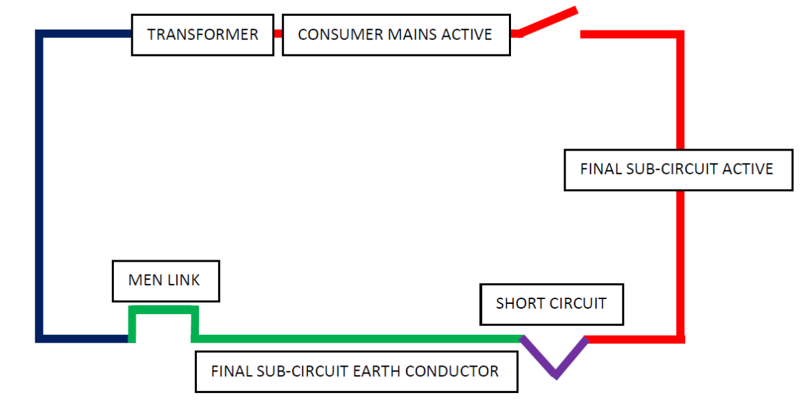
Avoiding damage to earth cables during faults
Correct sizing of protective earth (PE) cables is extremely important in order to safely clear phase-to-earth faults. When a fault occurs there are high levels of thermal energy, referred to as Joule Integral, generated during the clearing time of the protective device which operates to disconnect the faulty equipment. This let-through energy should be compared with the maximum permissible thermal energy that a protective earth (PE) cable can withstand. This is the topic of this article.
Another important factor to consider when sizing PE cables is earth fault loop impedance, which means the impedance should be sufficiently low to allow adequate fault current to pass for the protective device to operate within a sufficiently short time which is again, for safety.
To avoid damage to a PE cable during a fault it must be capable of withstanding the let-through energy of the protective device. The thermal withstand capability depends on these factors:
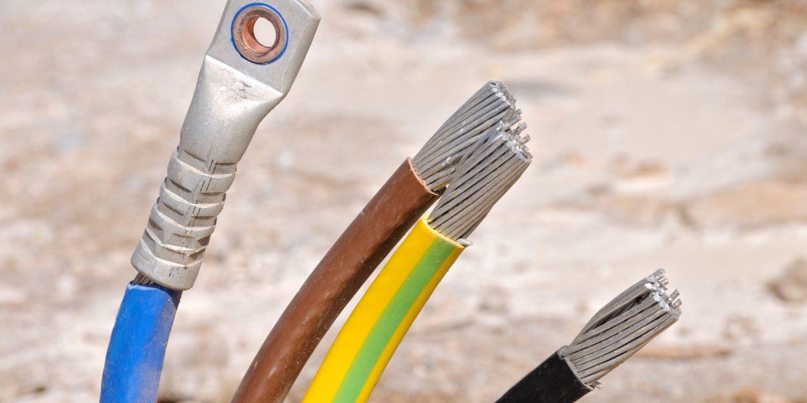
- Conductor cross-sectional area
- Conductor material (e.g. copper)
- Insulation type (e.g. PVC)
- Initial temperature at the inception of the fault
- Maximum temperature it can withstand without damage
Note that in some instances a PE cable may be a bare conductor without insulation.
It is also important to note not only the PE cable but that all components in the fault path such as terminations, joints and bonds must also have adequate thermal withstand capability.
How to calculate minimum earth conductor size
- Obtain the material constants for the conductor type from Table 1.
- Obtain the temperature limits for the cable type from Table 2.
- Determine initial temperature, θ0:
- Use Normal use temperature of the loaded phase cable – if the PE cable is combined inside a multicore cable or bunched with a phase conductor; otherwise
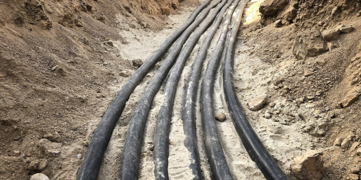
- Use ambient environment temperature (i.e., 25 ˚C for buried or 40 ˚C in air – check your local standards).
- Determine maximum short-circuit temperature, θM:
- Calculate k2 using equation 2.
- Calculate minimum conductor size S using equation 3.
There are example calculations at the end of this report.
Equations to use:
The fundamental equation 1 is given below where the left side is the let-through energy developed during the fault and the right side represents the energy withstand of the cable.
\(\int_{0}^{t_f} {i^2}_G \,dt \leq k^2S^2\) Equation 1
Where iG is the instantaneous earth fault current, tf is the fault clearing time, S is the cross-sectional area of the conductor (mm2) and k2 is a factor that considers the resistivity, temperature coefficient and heat capacity of the conductor material, the initial temperature of the protective conductor at the inception of the fault and maximum permissible short-time temperature of the cable.
The equation for the factor k2 is given as follows.
\(k^2 = \frac{c}{\alpha_0\rho_0}\ln{\frac{1+\alpha_0\theta_M}{1+\theta_0\alpha_0}}\) Equation 2
Where α0 is the temperature coefficient of resistivity of the conductor material, c is the volumetric heat capacity, ρ0 resistivity, θ0 is initial temperature and θM is maximum permissible short-time temperature. Typical values of constants for calculating k2 are given in Table 1 and Table 2.
Note that smaller values for the k2 factor determine larger PE conductor sizes for the same fault current and clearing time.
The analytical evaluation the left side of equation 1 is quite difficult because the fault current iG is asymmetrical due to the transient DC component. Therefore, the IEC Standard [1] has provided a simplified equation 3 below to determine the minimum cross-sectional area of a PE conductor assuming adiabatic conditions and suitable only for fault clearing times within 5 seconds.
\(S \geq \frac{I_G}{k}\sqrt{t_f}\) Equation 3
The minimum conductor size given by equation 3 should be rounded up to the nearest commercially available size. Of course, equation 3 can be used for different types of protective conductors and not only for cables including armors, metallic sheaths, screens etc.
Initial temperature
The initial temperature of the PE cable may be taken as either:
- Same as the operating temperature of the phase cables.
This assumption is appropriate for PE cables integrated with the phase conductors (i.e., multicore cables) but too conservative for separate PE cables which will result in oversizing.
- The ambient temperature of the environment.
This assumption is appropriate when the PE cable is separate and not bunched with the load-carrying phase cables.
Non-adiabatic calculations
The adiabatic equation 3 assumes the let-through energy of the protective device is entirely accumulated within the PE cable during the fault and that none of heat generated is dissipated to the outside environment. According to the NFPA National Electrical Code [3] the adiabatic assumption is reasonable and practical for most cases where they state that the non-adiabatic condition is only useful in practice for very small conductors of 10 mm2 or less.
The IEC Standard [2] provides a non-adiabatic method and set of equations for determining minimum conductor size. In practical terms the non-adiabatic equations are useful for short-circuit ratings of power cable phase conductors and metallic components.
Reference data
Table 1. Material constants for calculation of k2
| Material | Resistivity, ρ0 (Ω.mm) | Temperature coefficient of resistivity, α0 (per K at 20 ˚C) | Volumetric heat capacity, c (J.mm-3.K-1) |
|
Conductors - Copper - Aluminium |
1.7241 x 10⁵ 2.8264 x 10⁵ |
3.93 x 10³ 4.03 x 10³ |
3.45 x 10³ 2.422 x 10³ |
|
Sheaths and armour - Lead or lead alloy - Steel - Stainless steel - Aluminium |
21.4 x 10⁵ 13.8 x 10⁵ 70 x 105 2.84 x 10⁵ |
4 x 10³ 4.5 x 10³ Negligible 4.03 x 10³ |
1.44 x 10³ 3.756 x 10³ 3.756 x 10³ 2.422 x 10³ |
Table 2. Temperature limits for insulating materials in contact with conductors
| Insulation type | Operating temperatures of conductors | |
| Normal use (˚C) – Note 1 | Short time maximum, θM (˚C) – Note 2 | |
|
Thermoplastic: V-75, HFI-75-TP, TPE-75, V-90, HFI-90-TP, TP-90, V-90HT - Up to and including 300 mm2 - Greater than 300 mm2 |
75 75 |
140 160 |
|
Polyethylene: PE, LLDPE - Up to and including 300 mm2 - Greater than 300 mm2 |
70 70 |
140 160 |
|
Cross-linked elastomeric: - R-EP-90, R-CPE-90, R-HF-90, R-CSP-90 - R-HF-110, R-E-110 |
90 110 |
250 250 |
|
Cross-linked polyolefin (XLPE): - X-90, X-90UV, X-HF-90 - X-HF-110 |
90 110 |
250 250 |
| Mineral-insulated metal-sheathed (MIMS) | 100 | 250 (conservative) |
| High temperature: R-S-150 and Type 150 fibrous | 150 | 350 |
| Paper | 85 | 250 |
Notes:
1. The Normal use temperature relates to the sustained current-carrying capacity.
2. The Short time maximum temperature is permitted under short-circuit conditions.
Worked examples - calculating minimum earth size
Example 1 – separate earth cable
Size an underground protective earth cable which is separated away from the main power cables and made up of copper conductors and will be PVC V-75 insulated. The maximum earth fault current is 3.5 kA and associated fault clearing time is 0.3 seconds.
Solution
The material constants from Table 1 are:
Temperature coefficient α0 = 3.93 x 10⁻³ per K at ˚C
Volumetric heat capacity c = 3.45 x 10⁻³ J.mm-3.K-1
Resistivity ρ0 = 1.7241 x 10⁻⁵ Ω.mm
The initial and maximum temperatures are:
Initial temperature θ0 = 25 ˚C which is assumed to be the temperature of the soil (environment).
Final temperature θM = 140 ˚C taken from Table 2 for conductor sizes ≤ 300 mm2.
The k2 factor is calculated using equation 2 to be 17549.
Therefore, using equation 3 the minimum size of the conductor should be > 14.47 mm2. The nearest available trade size is 16 mm2.
Note if initial temperature is assumed to be 75 ˚C then the minimum size is 20.02 mm2 which leads to a larger earth cable size than necessary.
Example 2 – integrated earth cable
Determine the minimum protective earth cable with a copper conductor which is integrated inside a low-voltage XLPE (X-90) insulated multicore power cable. The maximum earth fault current is 5 kA and associated fault clearing time is 0.4 seconds.
Solution
The material constants are same as for Example 1.
The initial and maximum temperatures are:
Initial temperature θ0 = 90 ˚C which is same as the normal operating temperature of the cable.
Final temperature θM = 250 ˚C taken from Table 2 for XLPE insulated cables.
The k2 factor is calculated using equation 2 to be 19426.
Therefore, using equation 3 the minimum size of the conductor should be > 22.69 mm2. The nearest available trade size is 25 mm2.
References:
- IEC Standard 60364-5-54 Electrical Installations of Buildings – Part 5-54: Selection And Erection Of Electrical Equipment – Earthing Arrangements, Protective Conductors And Protective Bonding Conductors.
- IEC Standard 949 Calculation of thermal permissible short-circuit currents, taking into account non-adiabatic heating effects.
- National Electrical Code, NFPA 70, 2011.