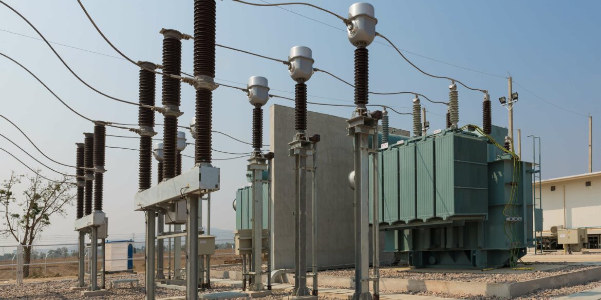
Structures need to be protected from the damaging effects of direct lightning strikes using a lightning protection system (LPS) typically constructed from air-terminations, network of down-conductors and a buried earthing system. When lightning strikes an air-termination the high-frequency and high-magnitude impulse current is carried downwards and then is dissipated into the ground, ideally in a safe and non-destructive manner.
Lightning strikes and the resultant impulse currents vary considerably. The standard IEC 62305 [ref. 2] provides expected (probable) models of lightning currents, along with time constants and peak current values, to be used for the design of an LPS and predicting the effects of a lightning strike.
This report describes the basics of an LPS system and outlines important relevant facts about lightning currents. Then it explains how a lightning strike on an LPS can be modelled using an equivalent sinusoid with a frequency ranging from 25 kHz up to 1 MHz which gives similar results to a time-domain approach.
In summary the equivalent single frequencies and RMS currents for standard lightning impulse current waveforms are given by the table below.
| Type of lightning impulse | Front time constant, T1 (µs) | Equivalent sinusoidal waveform | |
|---|---|---|---|
| Equivalent frequency (kHz) | Effective RMS current (kA) | ||
| First positive | 10 | 25 | 141.421 |
| First negative | 1 | 250 | 70.711 |
| Subsequent negative | 0.25 | 1000 | 35.355 |
Note that first negative type strikes (250 kHz equivalent sinusoid) account for most lightning strikes [ref. 1] therefore it may be necessary to only model lightning effects for this case.
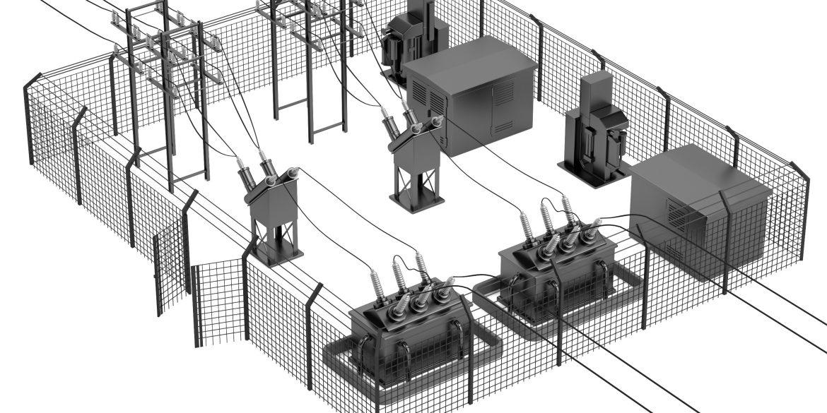
Protecting against direct lightning strikes
Lightning strikes to structures are hazardous to people, damaging to the structures themselves, their contents and installations as well as the interconnected lines. That is why the application of lightning protection systems is essential.
A typical lightning protection system (LPS) consists of an air-termination system (lightning rods), a down-conductor system and buried earthing system. When lightning strikes a lightning rod the lightning current (of high-magnitude and high-frequency) is carried downward through the down-conductors and dissipated safely into the earth.
The electrical design requirements of the lightning protection system are as follows:
- The air terminations should be of adequate height and the quantity and locations of lightning rods should be appropriate to intercept lightning strikes. This is usually achieved by using the rolling sphere method of calculation.
- The down-conductor network should be adequately sized to withstand the lightning current, the path of current flow to ground should be as direct as possible and separation distance of down-conductors to other conductive objects should be sufficient to avoid dangerous flashovers.
- The buried earthing system should dissipate the lightning current safely, minimising the touch and step voltages for the frequency range of lightning.
The behaviour of earthing systems towards lightning currents (high-frequency, high magnitude impulse) is very different compared with power system fault currents (low-frequency, sinusoids) which is due to the very different nature of the lightning current waveforms which are explained next.
Properties of lightning currents
Lightning strikes and their current waveforms come in different forms and are not entirely predictable. Lightning strikes can either be upward or downward initiated and either negative or positive polarity. Downward flashes occur in flat territory and to lower structures. Upward flashes are more prominent for exposed or higher structures. The probability of direct strike to a structure increases with structure height.
All impulse current parameters of upward flashes are less than those of downward flashes and a higher long stroke charge of upward flashes is not confirmed. Therefore, the lightning current parameters of upward flashes are considered to be covered by the maximum values for downward flashes.
About 85 to 95 % of the flashes to structures having heights less than about 100 metres on flat or rolling terrain are negative downward. The other 5 to 15 % are either negative upward or positive. Thus, from an electrical transmission or substation viewpoint, except for mountainous terrain or very high river crossing towers, the negative downward flash is of primary concern. Only 2 to 10 % of total flashes are positive polarity [ref. 1].
A lightning strike consists of one or more different strokes (often combined):
- impulses (short strokes) with duration less than 2 ms.
- long strokes with duration longer than 2 ms.
Strokes have a polarity (positive or negative) and a position (order) during the flash. A polarity ratio of 10 % positive and 90 % negative strokes is always assumed in the absence of local information.

Figure 1 – Possible components of downward flashes
A downward flash consists of a first impulse, which can be followed by subsequent impulses. One or more impulses may be followed by a long stroke.

Figure 2 – Possible components of upward flashes
An upward flash consists of a first long stroke with or without multiple superimposed impulses. One or more impulses may be followed by a long stroke.
The standard lightning current waveform
Short strokes of downward flashes have the highest peak current magnitude.

Figure 3 – Lightning current impulse (short stroke)
The short strokes current waveform can be approximated using the Heidler function:
\(f(t) = \frac{f_{peak}}{k}\frac{\left(\frac{t}{\tau_1}\right)^n}{1+\left(\frac{t}{\tau_1}\right)^n}\ \ e^{-\frac{t}{\tau_2}}\)
Where:
- \(f_{peak}\) (V or A) is peak value (1 for normalised function).
- k is corrective factor of the peak value.
- n is steepness factor.
- \(\tau_1\) is front time or rise to peak parameter \(\mu s\).
- \(\tau_2\) is front time or rise to peak parameter \(\mu s\).
The current steepness factor n is given a value of 10 in Annex B of Standard IEC 62305-1:2010 [ref. 2].
The front and decay time parameters τ1 and τ2 are related (but different) to the front and decay time values T1 and T2 displayed in Figure 3 in case of a lightning current impulse.
T1 is a virtual parameter defined as 1.25 times the time interval between the instants when the 10 % and 90 % of the peak values are reached.
T2 is a virtual parameter defined as the time interval between the virtual origin and the instant at which the current has decreased to 50 % of the peak value on the tail.
The values for variables used with the Heidler function are given by the table below [ref. 2].
| Maximum lightning impulse waveform parameters per IEC 62305-1:2010 [ref. 2] | ||||||||
|---|---|---|---|---|---|---|---|---|
| Type of impulse | Peak current LPL I (kA) | Peak current LPL II (kA) | Peak current LPL III, IV (kA) | Peak current correction factor, k | Front time constant, T1 (µs) | Tail time constant, T2 (µs) | Front time parameter τ1 (µs) | Decay time parameter τ2 (µs) |
| First positive | 200 | 150 | 100 | 0.93 | 10 | 350 | 19 | 485 |
| First negative | 100 | 75 | 50 | 0.986 | 1 | 200 | 1.82 | 285 |
| Subsequent negative | 50 | 37.5 | 25 | 0.993 | 0.25 | 100 | 0.454 | 143 |
An equivalent single frequency to model lightning short strokes
The maximum impulse current values of lightning current parameters for the different protection levels are generally used for design lightning systems components and for safety calculations.
A single equivalent frequency can be used to model a lightning impulse current waveform and achieve similar results to a time domain approach [ref. 3]. The sinusoidal waveform is derived such that it has similar (or shorter) rise time and a similar (or higher) peak value as the lightning current impulse waveform.
The equivalent frequency is derived using T1 the front time to impulse current as follows:
\(f_{eq}=\frac{1}{4T_1}\)
Essentially the lightning impulse current waveform is chopped after the front time T1.
The equivalent effective current of the impulse is as follows:
\(I_{eff}=\frac{I_{peak}}{\sqrt{2}}\)
Figure 4 above shows a plot of the Heidler function (in blue) and an equivalent 250 kHz sinusoidal waveform (in orange) for a first-negative lightning impulse current. As can be seen, the rise-time of both waveforms is very similar, and the peak current is obviously matched. Therefore, the equivalent sinusoid is considered as appropriate for determining the worst-case effects on an LPS of a lightning impulse current.

Figure 4 – Heidler function for first negative impulse current and equivalent 250 kHz sinusoidal waveform
References:
[1] Insulation Coordination for Power Systems, Hileman, A. R.
[2] IEC 62305-1:2010 Protection against lightning – Part 1: General principles.
[3] Calculation of Lightning Effect in the Frequency Domain with a Program based on Hybrid Methods, CIGRE International Colloquium on Lightning and Power Systems 2016.