Call Us: 1300 093 795
Email Us: enquiry@elek.com.au

  • Login Cable Pro
Menu
  • Login Cable Pro
Electrotechnik
  • Software
    • Cable Pro Web (AU)
    • Cable Pro Web (UK)
    • Protection Coordination
    • SafeGrid Earthing
    • Cable High Voltage
    • Cable Pulling
    • Bare Conductor Ratings
    • Power Bundle
  • Resources
    • Article Categories
      • Low Voltage Design
      • Earthing Design
      • High Voltage Cable Design
      • Electrical Software
      • Arc Flash Studies
    • Tutorials
    • Free Calculators
      • Cable Sizing AS3008
      • Cable Sizing BS7671
      • Voltage Drop
      • Arc Flash
      • Earth Cable Sizing
      • Fault Loop Impedance
      • Earth Grid Resistance
      • Earth Grid Conductor Sizing
      • Earthing Rods Resistance
      • Lightning Protection Design
      • Relay Tripping Time
      • Equivalent Thermal Resistance
    • Courses
      • SafeGrid Earthing Software Course
    • Technical Publications
    • Training and Certification
  • Support
    • Support Overview
    • Help Portal
  • About
    • About Us
    • Contact Us
    • Careers
    • Reseller & Partner Program
  • Login
    • Cable Pro Web Login
    • Training Courses Login
    • Customer Licence Portal
  • TRY FOR FREE
  • SCHEDULE A DEMO
  • TRY FOR FREE
  • SCHEDULE A DEMO
  • TRY FOR FREE
Menu
  • Software
    • Cable Pro Web (AU)
    • Cable Pro Web (UK)
    • Protection Coordination
    • SafeGrid Earthing
    • Cable High Voltage
    • Cable Pulling
    • Bare Conductor Ratings
    • Power Bundle
  • Resources
    • Article Categories
      • Low Voltage Design
      • Earthing Design
      • High Voltage Cable Design
      • Electrical Software
      • Arc Flash Studies
    • Tutorials
    • Free Calculators
      • Cable Sizing AS3008
      • Cable Sizing BS7671
      • Voltage Drop
      • Arc Flash
      • Earth Cable Sizing
      • Fault Loop Impedance
      • Earth Grid Resistance
      • Earth Grid Conductor Sizing
      • Earthing Rods Resistance
      • Lightning Protection Design
      • Relay Tripping Time
      • Equivalent Thermal Resistance
    • Courses
      • SafeGrid Earthing Software Course
    • Technical Publications
    • Training and Certification
  • Support
    • Support Overview
    • Help Portal
  • About
    • About Us
    • Contact Us
    • Careers
    • Reseller & Partner Program
  • Login
    • Cable Pro Web Login
    • Training Courses Login
    • Customer Licence Portal
  • TRY FOR FREE
  • SCHEDULE A DEMO
  • TRY FOR FREE
  • SCHEDULE A DEMO
  • TRY FOR FREE

Home / Articles / Earthing Design

Extensive Study of Earthing Grids

Parametric study of earthing system performance. 

Overview

An extensive study of earthing grids using SafeGrid software designed for determining performance of grids of arbitrary geometrical configuration in two layer soils has been undertaken.  The study confirms work by Dawalibi and Mukhedkar undertaken using similar software called CDEGS®.

A variety of earth grid configurations and soil models were analysed.  Important physical parameters have been varied and results pertaining to safety have been calculated; including ground resistances, ground potential rise, touch and step potentials.

The results of this study aim to prove the following:

  • Simplified methods of analysis such as the equations presented in IEEE Std. 80 make too many assumptions and fail to accurately predict performance of earthing systems.
  • The results obtained agree with the physical theory and match closely with results from other similar research and studies.

Software

SafeGrid algorithm based on proven science and confirmed by field tests over several decades.

Modelling capabilities:

  • Grounding systems of arbitrary geometrical configurations.
  • Two-layer soil modelling.
  • Three-dimensional (3D) analysis of surface, touch and step potentials.

Soil Model

There are two types of soil models used; uniform soil and two-layer soil.

Accurate modelling of a grounding system requires the use of a two-layer soil model.  This is because the ground resistance, step and touch potentials are a function of both top and bottom soil layers.

The two-layer model consists of an upper layer of resistivity ρ1 of finite thickness as well as a lower layer of resistivity ρ2 to an infinite depth.

IEEE Std 80 states the representation of a grounding electrode based on an equivalent two-layer earth model is sufficient for designing a safe grounding system.

DescriptionReflection factor, K1Top layer resistivity, ρ1 (Ω.m)Bottom layer resistivity, ρ2 (Ω.m)
Uniform0100100
Low on high0.91001900
0.5100300
High on low-0.91005.26
-0.510033.33
Table 1. Soil models studied

1 Reflection factor, K = (ρ2 – ρ1)/ (ρ2 + ρ1)

Grid Cases Analysed

The simple earthing grids shown in Table 2 were analysed in detail.

SafeGrid can model any arbitrary grounding conductor configuration.

These earthing grids generally consisted of square or rectangular grids with meshes containing equally spaced and conductors of identical length.

Depth of burial of earth grids was varied from 0.01 m up to 100 m.  For two-layer soil models the top layer depth was varied from 0.1 m up to 100 m.

The values from calculation results shown in Table 2 are for fixed parameter values as indicated.  These parameters were for the same simple grids varied during the parametric analysis.

Table 2. Grid cases analysed. Common parameters soil resistivity = 100 Ω.m (uniform), fault current = 1000 A.

Results

Surface, touch and step potentials

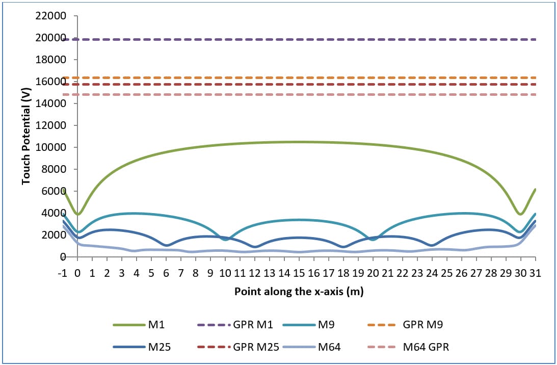
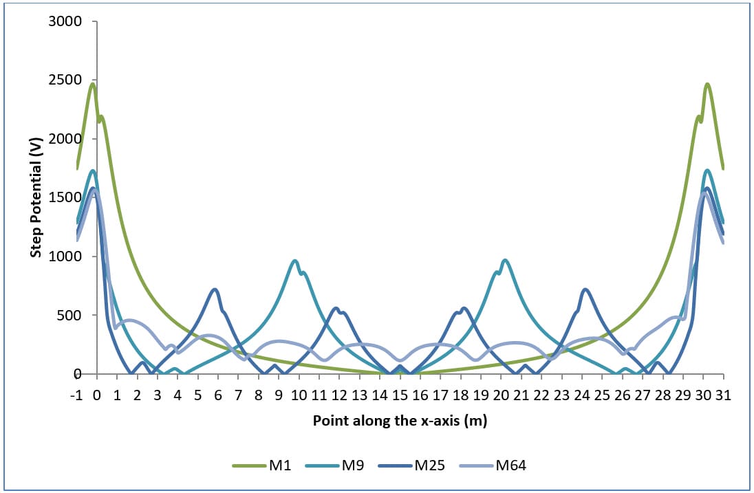
Plots of earth surface potentials, touch potentials and step potentials for various grid configurations are given in Figures 1, 2 and 3 respectively.

Increasing the number of conductors (or meshes) has the following affects:

  • Decreases the grid resistance (R).
  • Decreases the grid potential rise (GPR) since GPR = R * Fault Current.
  • Maximum earth surface potential decreases.
  • Touch potentials are reduced (Figure 2).
  • Worst touch potentials move towards the edge of the grid. Shown by the increase in concavity of curves in Figure 2 for increase in number of meshes. 

Note this final observation applies for uniform soil, positive reflection factor K and uniformly spaced grid conductors.  Otherwise it is difficult to predict the location of the worst touch potentials.
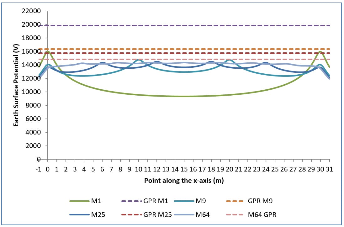
Figure 1. Surface potentials – grid depth of burial = 0.5 m, soil model = 100 Ω.m (uniform), fault current = 10 kA.
Figure 2. Touch potentials – grid depth of burial = 0.5 m, soil model = 100 Ω.m (uniform), fault current = 10 kA.
Figure 3. Step potentials – grid depth of burial = 0.5 m, soil model = 100 Ω.m (uniform), fault current = 10 kA.

Current density along conductors

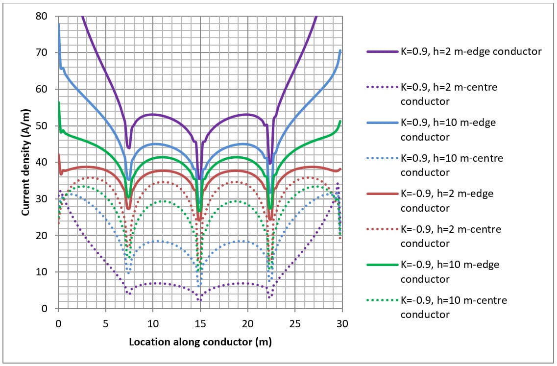
The current density for conductors is shown in Figures 4, 5 and 6 for various grid arrangements and soil resistivity structures.

The grid fault current applied is dependent on the total length of grid conductors for a particular arrangement where 1000 A is applied for every 30 metres of conductor.  For example, for a single mesh which consists of 4 x 30 m conductors the fault current applied was 4 x 1000 A.

The current density distribution along grid conductors is not uniform but is a complex function which varies according to:

  1. Grid arrangement (i.e. the number of meshes etc.)
  2. Location of the conductor with respect to other conductors; and
  3. Soil resistivity structure

When the top layer soil resistivity is lower than the bottom layer (i.e. K>0) the current density is concentrated towards the ends of the conductors.  This is because the current remains within the top soil layer and spreads out as it dissipates into the soil.

When the lower layer soil resistivity is higher than the top layer (i.e. K<0) the current density at the centre of the conductors can be just as high as at the ends.  This is because the fault current escapes directly downwards toward the lower resistivity bottom layer.

The current dissipation of conductors along the edge is higher (solid lines in Figure 5 and Figure 6) than for conductors in the centre (dashed lines in Figure 5 and Figure 6) of the buried earth grid.
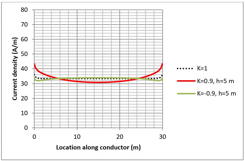
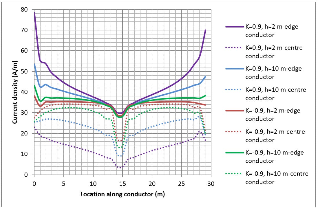
Figure 4. Single mesh current density along conductor. Fault current = 4 x 1000 A
Figure 5 Four mesh (M4) current density along conductors. Fault current = 6 x 1000 A
Figure 6 Sixteen mesh (M16) current density along conductors. Fault current = 10 x 1000 A

Effect of top soil layer on grid resistance

Figure 7 and Figure 8 show for a simple 30 x 30 metre mesh (M4 and M16) buried at 0.5 metres how grid resistance varies with the thickness of the top soil layer.

Top layer soil resistivity is fixed while the bottom soil layer resistivity is varied to achieve different reflection factors (K).  The grid resistance is calculated for varying depths of the top soil layer.

Changing the top soil layer depth has the following effects:

  • For a uniform soil model (control case) there is no effect on grid resistance.
  • For low on high soil model (K>0) as the depth of the top soil layer is increased grid resistance goes down.
  • For high on low soil model (K<0) as the depth of the top soil layer is increased grid resistance goes up.
  • As the depth of the top layer approaches infinity then the grid resistance converges with the uniform soil model.

Note the abrupt change in grid resistance for all cases at top soil layer depth of 0.5 m (which corresponds to the depth of burial of grid).
It is shown that grid resistance is influenced by the bottom soil layer especially for high resistivity bottom soil layers (K>0).  The influence of the bottom soil layer on grid resistance can be neglected at high depths (around two or more times the overall grid diameter).
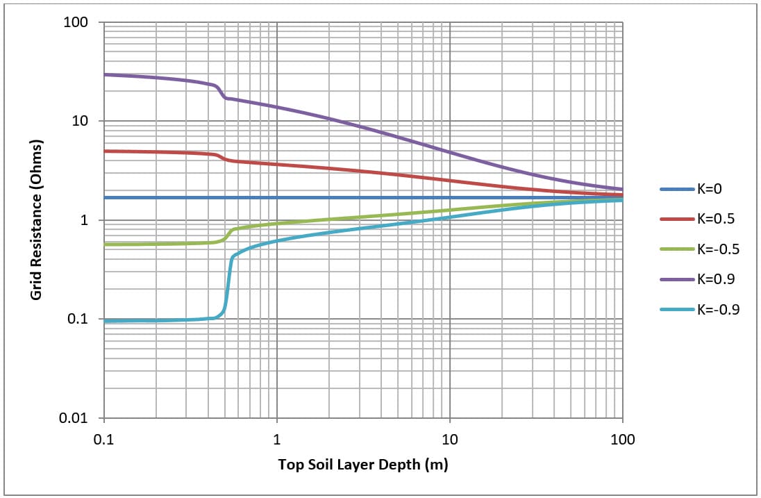
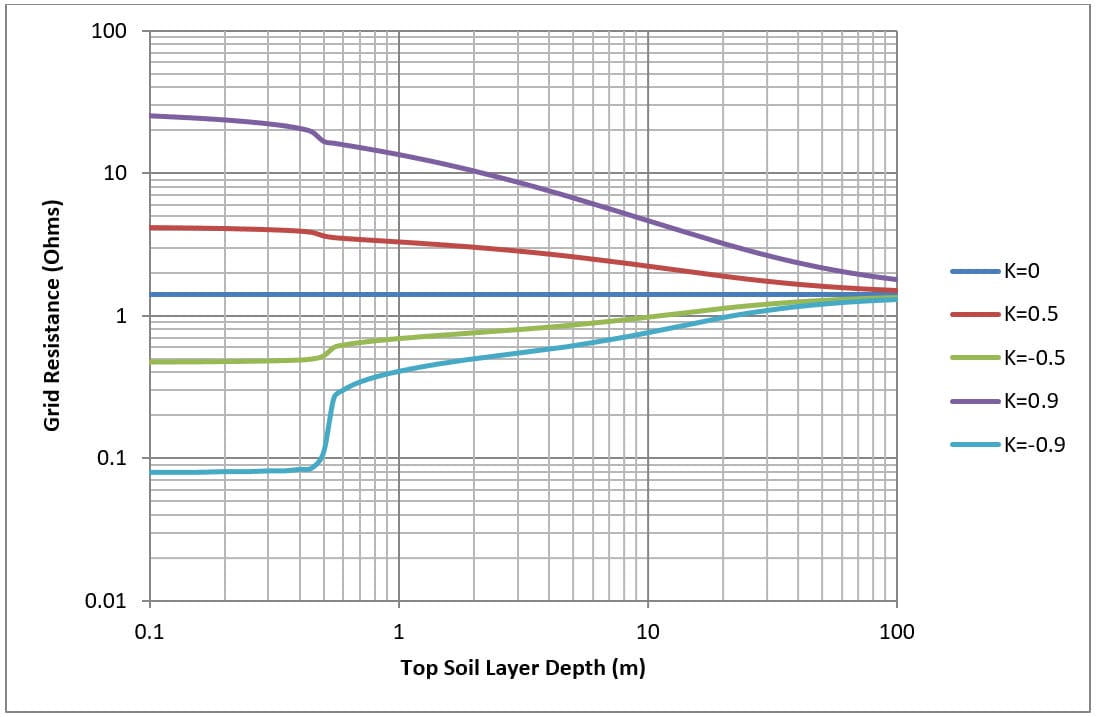
Figure 7. Four mesh (M4) top soil layer depth versus grid resistance for various soil models.
Figure 8. Sixteen mesh (M16) top soil layer depth versus grid resistance for various soil models.

Effect of depth of burial of grid on grid resistance

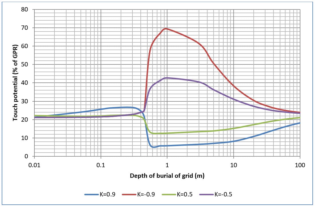
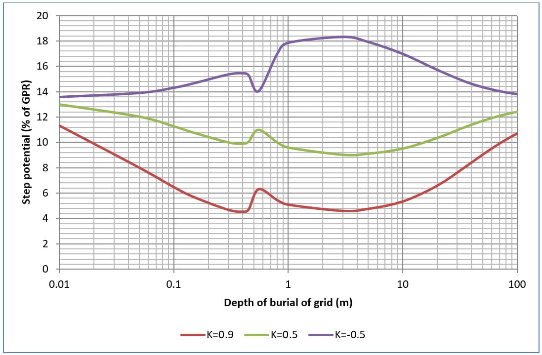
Figures 9, 10, 11 and 12 shows the effects on touch and step potentials of changing the depth of burial of four and sixteen mesh grids in two-layer soil.

In general with increasing depth in burial both touch and step potentials increase up to a maximum value then back down again.

The maximum touch potentials occur when the top layer soil resistivity is significantly greater than the bottom layer soil resistivity (i.e. when K=-0.9).

The maximum touch potential is reduced with an increase in the number of grid meshes.
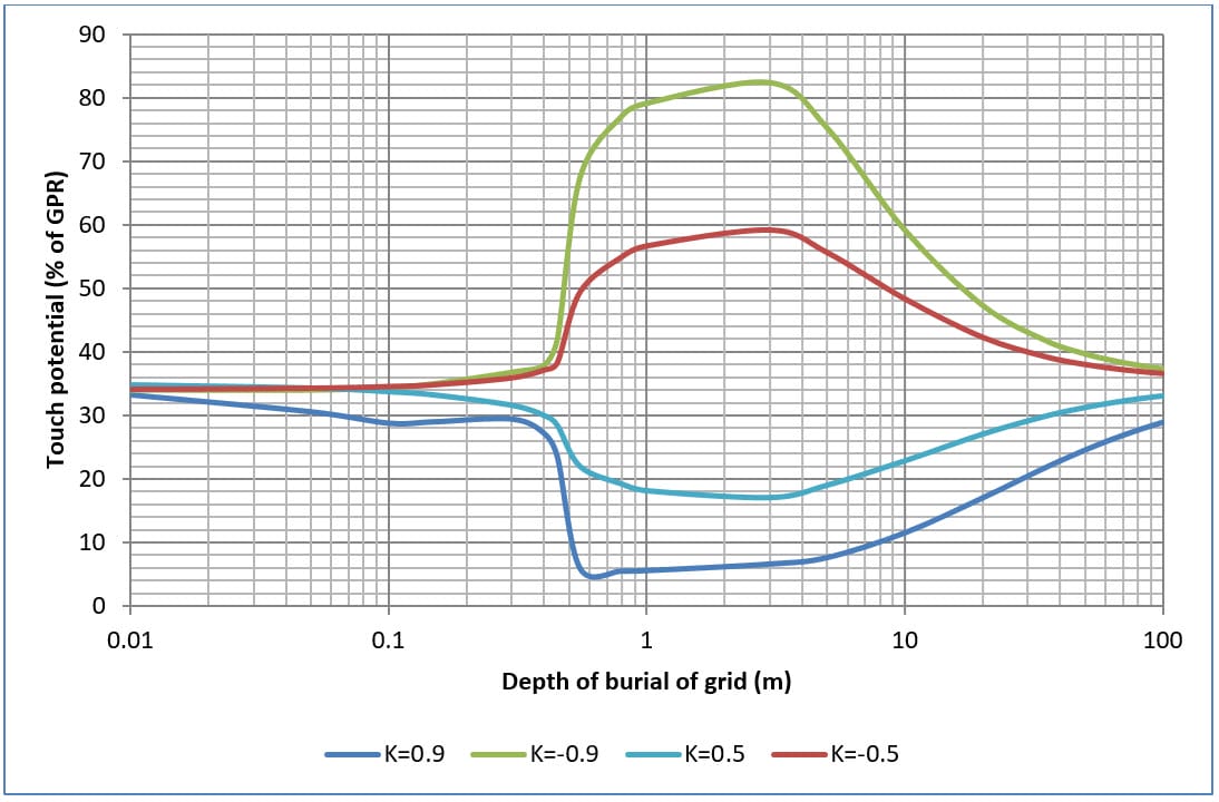
Figure 9. Four mesh (M4) depth of burial of grid versus touch potential (% of GPR) for various soil models.
Figure 10. Four mesh (M4) depth of burial of grid versus step potential (% of GPR) for various soil models.
Figure 11. Sixteen mesh (M16) depth of burial of grid versus touch potential (% of GPR) for various soil models.
Figure 12. Sixteen mesh (M16) depth of burial of grid versus step potential (% of GPR) for various soil models.

Conclusions

Accurate determination of grounding grid performance is imperative for providing most importantly safe as well as functional and economical designs.

It has been shown that the following parameters significantly influence the behaviour of earthing systems under fault conditions:

  • Grounding grid configuration.
  • Soil resistivity characteristics.
  • Burial depth of grounding grid.

These parameters directly affect the conductor current density (dissipation into the earth) which affects the grid potential rise (GPR), grid resistance, touch and step potentials.

Access to insightful software tools leads to optimal designs of grounding grids which are safe.

Visit the product page for the latest updates.

References

IEEE Guide for Safety in AC Substation Grounding, The Institute of Electrical and Electronics Engineers, Inc.

Dawalibi, F., Transmission Line Grounding. EL-2699, Research Project 1494-1. Montreal, Quebec, Canada, Safe Engineering Services Ltd. 1.

Dawalibi, F. and Mukhedkar, D., “Parametric analysis of grounding grids.” IEEE Transactions on Power Apparatus and Systems, Vol.PAS-98, No.5.

Kouteynikoff, P., “Numerical computation of the grounding resistance of substations and towers.” IEEE Transactions on Power Apparatus and Systems, Vol.PAS-99, No.3.

Salama, M.M.A. et. al., “A formula for resistance of substation grounding grid in two-layer soil.” IEEE Transactions on Power Delivery, Vol.10, No.3.
Related Articles:

elek article header ed fundamentals sm - Extensive Study of Earthing Grids

Fundamentals of
Earthing Design

This tutorial introduces key concepts used in the design of substation earthing/grounding systems. Important terminology is discussed including Grid Potential Rise, touch and step voltages and current distribution.

Read It Now
elek articles hv power cables - Extensive Study of Earthing Grids

High Voltage Power Cable
Current Ratings

The current rating of cables is affected by the installation conditions and the cable design and materials. In this report a parametric study of the factors which affect current ratings is presented.

Read It Now

SafeGrid Earthing Software

Easily design safe earthing systems in compliance with Standards.

Try For Free

Print this article:

Share on print
Print

SafeGrid Earthing Software

SafeGrid Earthing Software

Easily design safe earthing systems in compliance with Standards.

Try For Free

As used by:

For information or to speak with our helpful advisors

GET IN TOUCH

GET IN TOUCH

Electrotechnik-Footer

Electrical Power Systems Design & Analysis Software

FOLLOW US

social-fb
social-yt
social-li

SOFTWARE

  • Cable Pro Web
  • Protection Coordination
  • SafeGrid Earthing
  • Cable High Voltage
  • Cable Pulling
  • Line Rate
  • Power Bundle
Menu
  • Cable Pro Web
  • Protection Coordination
  • SafeGrid Earthing
  • Cable High Voltage
  • Cable Pulling
  • Line Rate
  • Power Bundle

RESOURCES & SUPPORT

  • Software Tutorials
  • Technical Publications
  • Training and Certification
  • Customer Licence Portal
Menu
  • Software Tutorials
  • Technical Publications
  • Training and Certification
  • Customer Licence Portal

CONTACT US

Email:
enquiry@elek.com.au

Need Help?
Lodge a Support Ticket

Phone:
1300 093 795
International:
+61 (0)2 8231 6673

FREE TECHNICAL NEWS

© 2022 All Rights Reserved    Privacy Policy Quality Policy Terms of Use

Schedule a Demo for Cable High Voltage

Look No Further. Get Started Today

  • This field is for validation purposes and should be left unchanged.
Schedule a Demo for SafeGrid Earthing

Look No Further. Get Started Today

  • This field is for validation purposes and should be left unchanged.
SafeGrid Earthing Free Trial
  • Fill out your details below to begin your trial. Once your information has been submitted you'll be able to download the software.

  • This field is for validation purposes and should be left unchanged.
Cable High Voltage Free Trial
  • Fill out your details below to begin your trial. Once your information has been submitted you'll be able to download the software.

  • This field is for validation purposes and should be left unchanged.
SafeGrid Earthing 14 day Free Trial

Fill out your details below to begin your trial. Once your information has been submitted you’ll be able to download the software.

  • Fill out your details below to begin your trial. Once your information has been submitted you'll be able to download the software.

  • This field is for validation purposes and should be left unchanged.

CLOSE

Cable High Voltage 14 day Free Trial

Fill out your details below to begin your trial. Once your information has been submitted you’ll be able to download the software.

  • Fill out your details below to begin your trial. Once your information has been submitted you'll be able to download the software.

  • This field is for validation purposes and should be left unchanged.

CLOSE

  • We strive for 100% customer satisfaction. If we fell short, please tell us more so we can address your concerns.

  • This field is for validation purposes and should be left unchanged.

If you do not wish to address your concerns here and prefer to post a review, click here.

Cable Pro (PC) Free Trial

Fill out your details below to begin your trial. Once your information has been submitted you’ll be able to download the software.

  • Fill out your details below to begin your trial. Once your information has been submitted you'll be able to download the software.

  • This field is for validation purposes and should be left unchanged.

CLOSE