Table of Contents
1. Overview of the benchmarks
The Annex H in IEEE Standard 80-2013 contains benchmark case results for comparing and evaluating software tools and methodologies used for the analysis of substation earthing.
The results compare the simple equations from IEEE Std. 80 with the results given by some of the commercially available software such as CDEGS – MALTZ and RESAP, ETAP Ground Grid Systems, SGW, SDWorkstation and WinIGS – Advanced Grounding Concepts.
The benchmarks are divided into two categories: soil analysis and grid analysis (resistance, touch and step voltages, transfer voltages).
SafeGrid Earthing Software (Multilayer Version 5.0) is an alternative to these other software packages and the results were computed and compared with the benchmark below.
2. Soil analysis
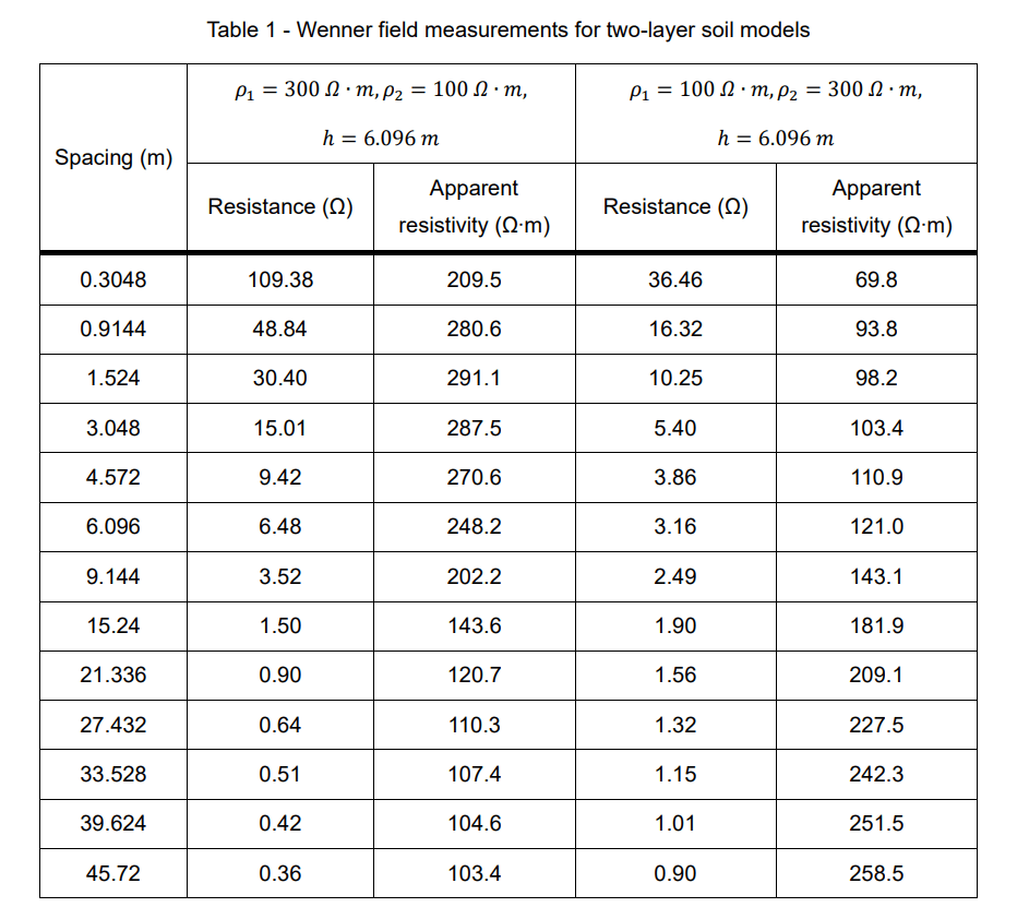
The following Table 1 shows the Wenner (Four-pin) measurements for two-layer soil models:
2.1 Two-layer soil models
Two-layer soil models derived from four-pin field measurements of Table 2 are shown as followed:
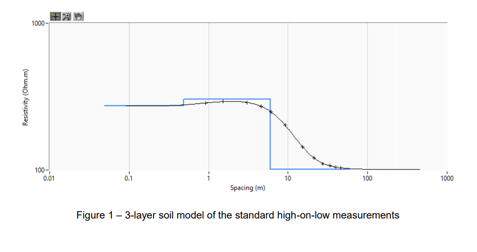
Multi-layer soil model has been investigated for these 2 soil models. It is found that for the high on low soil model a 3-layer soil model is more suitable. The RMSE decreases from 0.9 % (2-layer) to 0.22 % (3-layer). The 3-layer soil model is:
The 3-layer soil model result from the SafeGrid multilayer soil modelling program is in Figure 1.
3. Grounding system analysis
The grid current for all cases is 744.8A. The soil structure has been limited to uniform and two-layer soils. For consistency in comparing results between the programs, the touch and step voltages were evaluated at very specific points and with specific guidelines on the points evaluated to determine the worst-case voltages. For example, to determine the step voltage at the corner of the grid, the earth surface potentials were determined at points over the corner of the grid and 1m outside the grid along the diagonal. The step voltage was computed as the difference between the potentials at these two points. For cases where several points (i.e. a grid of points) were used to determine the worst-case touch voltage, the evaluated points were spaced 0.5m apart.
3.1 Grid 1 - symmetrically spaced and shaped grid, uniform soil, no ground rods
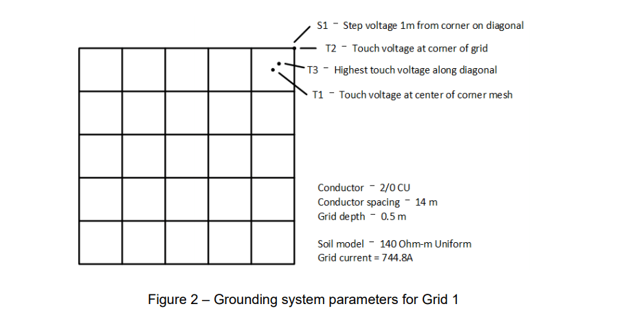
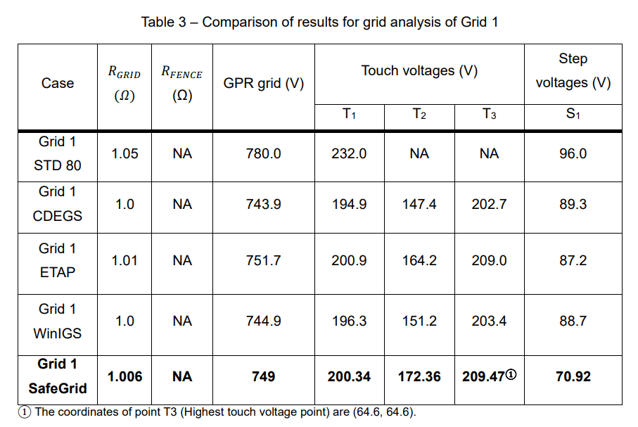
The ground grid for this comparison is shown in Figure 2. The equations in IEEE Std 80 compute the touch voltage at the centre of the corner mesh (T1), so this point was chosen for comparison. The actual maximum touch voltage for this grid shape might be on the diagonal near the centre of the corner mesh but located slightly nearer the perimeter of the grid (T3). For some cases, it might also be directly over the extreme corner (perimeter) of the grid (T2). Thus, these two points were also analysed for comparison. The equations in IEEE Std 80 compute the step voltage as the difference between the earth surface potential 1 m apart, with one point directly over the corner of the grid and the other on a diagonal and 1 m beyond the first point. Though the actual worst case step voltage might be at a different location, comparisons were limited to this one location (S1) for this case. The comparisons are shown in Table 3. For SafeGrid, grid resistance, GPR, touch voltages and step voltages are calculated over the whole area with 1 m separation.
The conductor area of 2/0 CU is 67.4 mm2.
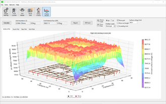
The surface voltages 3D plot from SafeGrid is shown in Figure 3. The touch and step voltages 2D plots are shown in Figure 4 and Figure 5 respectively.
3.2 Grid 2 - symmetrically spaced and shaped grid uniform soil, with ground rods
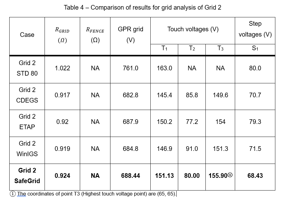
This case is the same as Grid 1, with the addition of twenty 7.5 m rods located at each intersection around the perimeter of the grid. The touch voltage and step voltage were computed at the same locations as for Grid 1. For SafeGrid, grid resistance, GPR, touch voltages and step voltages are calculated over the whole area with 1 m separation.
The surface voltages 3D plot from SafeGrid is shown in Figure 7. The touch and step voltages 2D plots are shown in Figure 8 and Figure 9 respectively.
3.3 Grid 3 - symmetrically spaced and shaped grid, two-layer soil, with ground rods
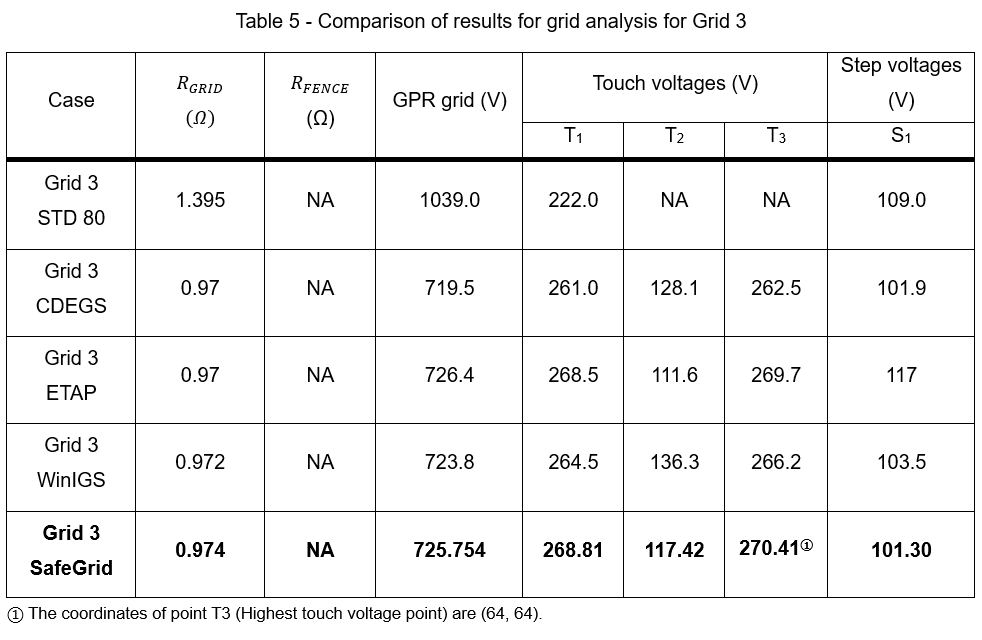
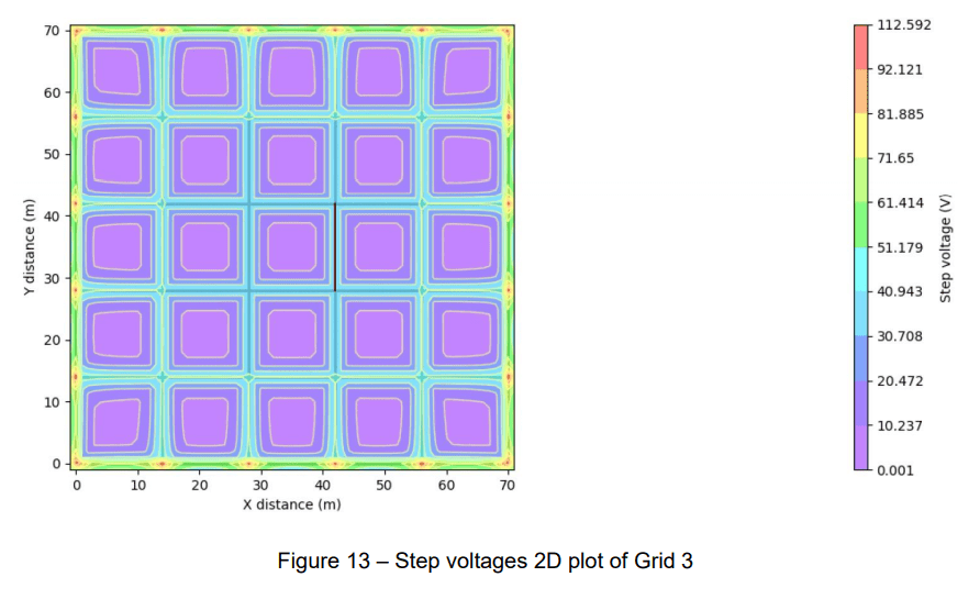
The ground grid for this comparison is the same as for Grid 2, except the soil model is changed to a two-layer soil with ρ_1=300 Ω∙m, ρ_2=100 Ω∙m, h = 6.096 m. The touch and step voltages were computed at the same location as for Grid 1. For SafeGrid, grid resistance, GPR, touch voltages and step voltages are calculated over the whole area with 1 m separation.
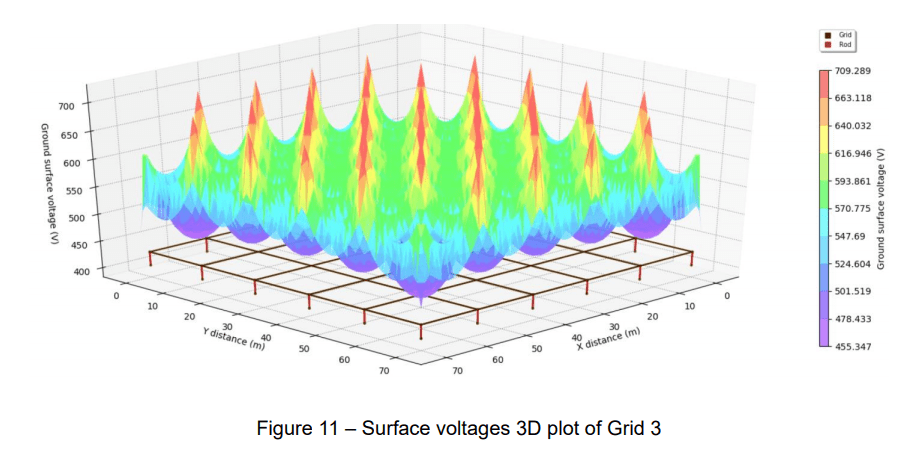
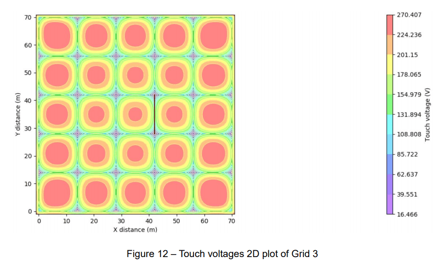
The surface voltages 3D plot from SafeGrid is shown in Figure 11. The touch and step voltages 2D plots are shown in Figure 12 and Figure 13 respectively.
3.4 Grid 4 - Symmetrically spaced and shaped grid, separately-grounded fence, two-layer soil, with ground rods
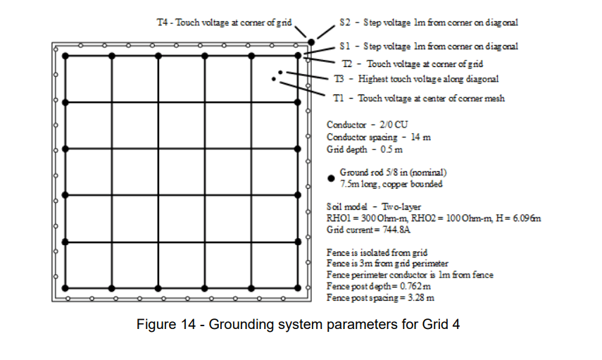
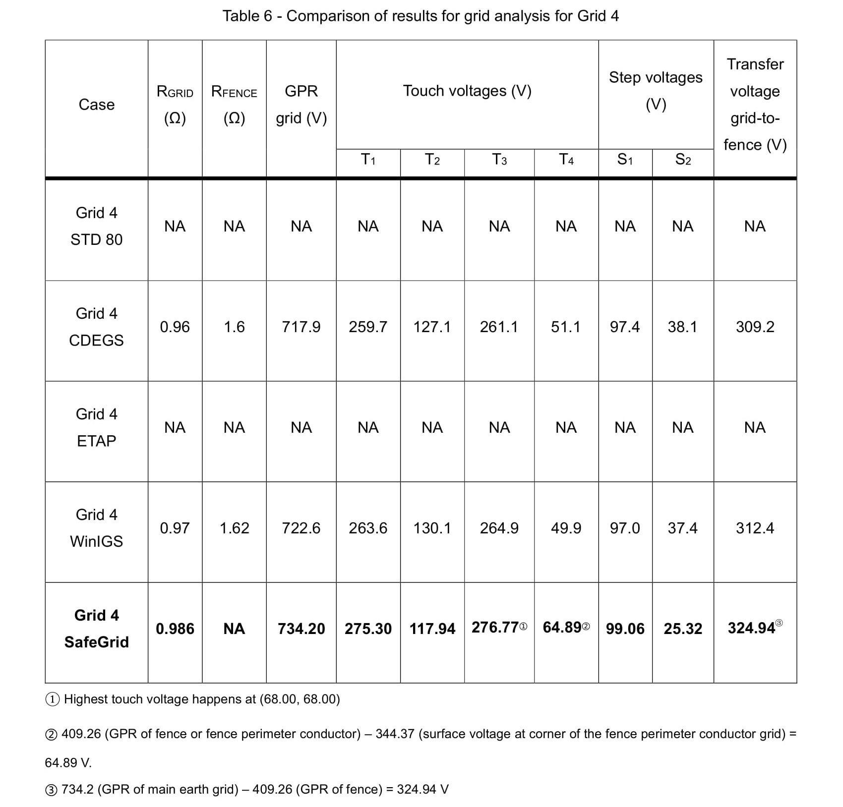
The ground grid for this comparison is the same as for Grid 3, except a separately-grounded fence is added, located 3 m outside the grid perimeter conductor, and with a fence perimeter ground conductor located 1 m outside the fence. The touch and step voltages were computed at similar location as for Grid 1. In this case, however, additional touch and step points were computed. For this case, touch voltages T1, T2, and T3 were computed as differences between the surface potentials at these points and the GPR of the main ground grid. T4 was computed as the difference between surface potential at the corner of the fence perimeter conductor and the GPR of the fence perimeter conductor (connected only to the separately-grounded fence). Step voltages S1 and S2 were computed as differences between earth surface potentials 1 m apart along the diagonal. S1 had the first point located over the corner of the perimeter conductor of the main grid, while S2 had the first point located over the outer (fence) perimeter conductor. The comparisons are shown in Table 6.
Insulated bonds between fence post and perimeter conductor are every 4 posts. Fence posts are connected with each other with insulated conductors in SafeGrid model. Touch voltages, step voltages, grid resistance and GPR are all calculated over the whole area with 1 m apart.
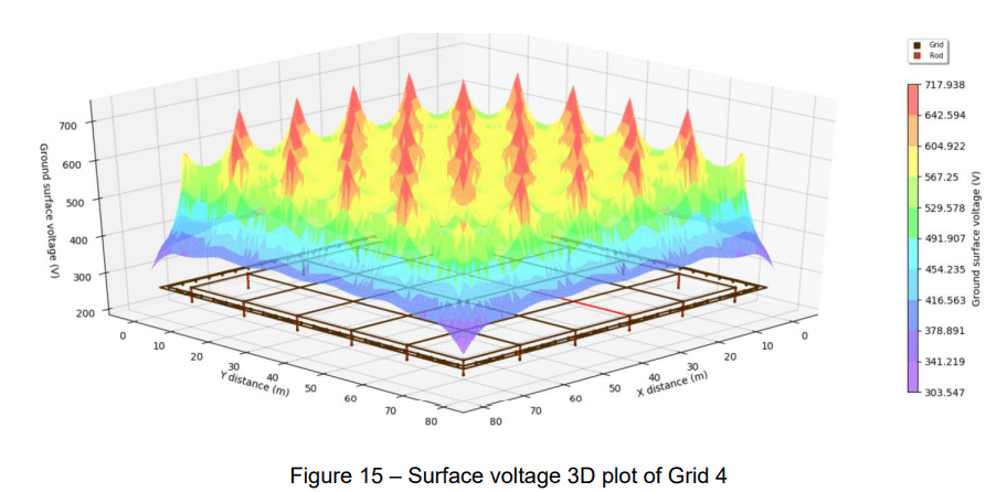
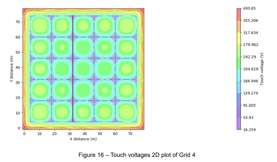
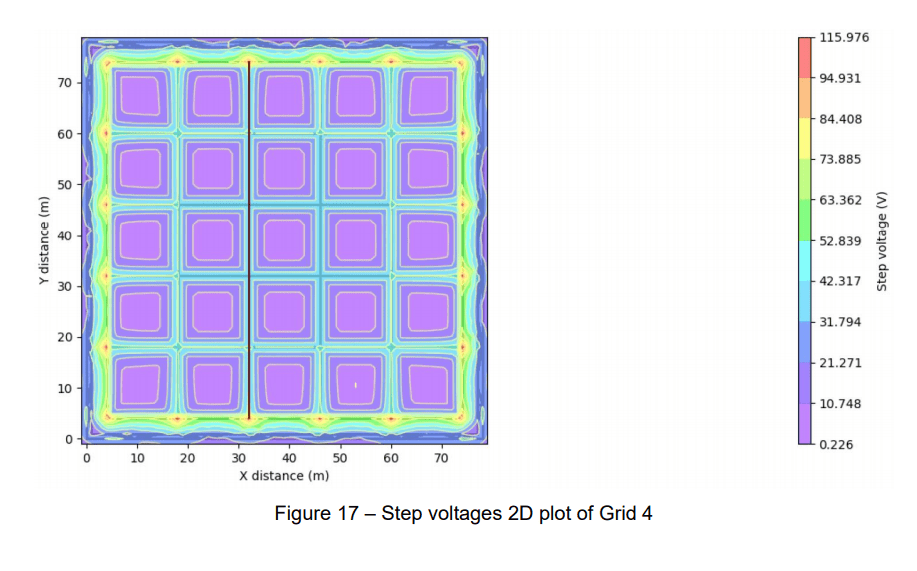
The surface voltages 3D plot from SafeGrid is shown in Figure 15. The touch and step voltages 2D plots are shown in Figure 16 and Figure 17 respectively.
3.5 Grid 5 - symmetrically spaced non-symmetrically shaped grid, fence grounded to main grid, two-layer soil, with ground rods
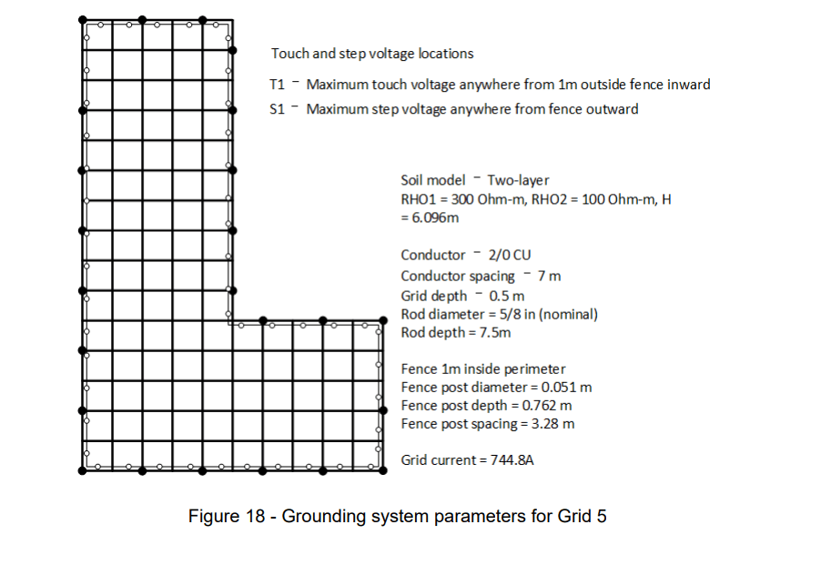
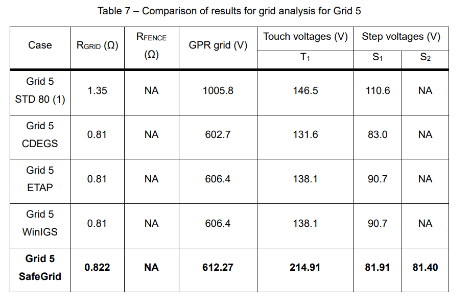
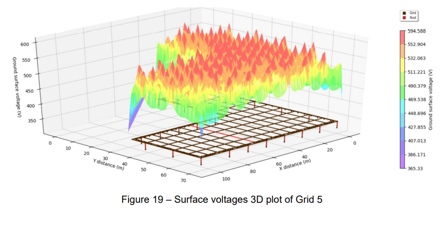
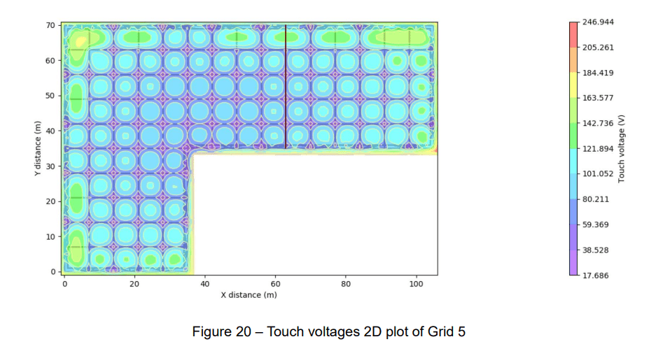
The ground grid for this comparison is shown in Figure 18. This grid is non-symmetrical in shape (L-shaped), though it still has symmetrically spaced grid conductors. It also has ground rods of uniform length at every other intersection around the perimeter and has a grounded fence within the confines of the main grid and bonded to the grid. The worst-case touch voltage was computed at all points 1 m apart within the fence, plus all points within reach (1 m) outside the fence. The worst-case step voltage (S1) was computed at all points 1 m apart within an area defined inward from 1 m outside the perimeter of the grid. For direct comparison, the step voltage (S2) was also compared by determining the difference between earth surface potentials 1 m apart along the diagonal at the upper left corner of the grid. The comparisons are shown in Table 7.
The surface voltages 3D plot from SafeGrid is shown in Figure 19. The touch and step voltages 2D plots are shown in Figure 20 and Figure 21 respectively.
3.6 Grid 6 - non-symmetrically spaced and shaped grid, non-orthogonal conductors, two-layer soil, with ground rods at random locations and unequal lengths
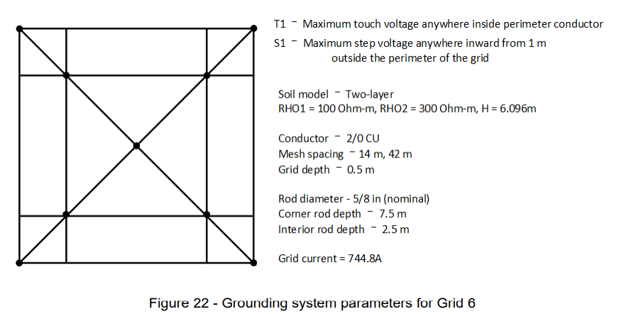
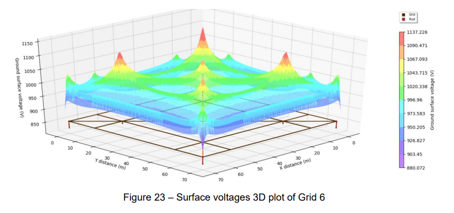
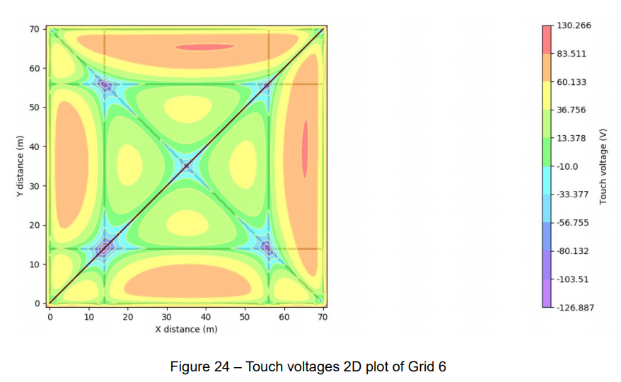
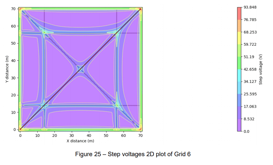
The final ground grid for comparison is similar to Grid 3, but with conductors on the diagonal and with corner grounds 7.5 m long and all other ground rods 2.5 m long. The soil model is changed to a two-layer soil with ρ1 = 100 Ω-m, ρ2 = 300 Ω-m, and h = 6.091 m (20 ft). See Figure 22. For the computer programs, the touch and step voltages were computed at numerous points to determine the worst case for each. The worst case touch voltage was computed at all points 0.5 m separation within the perimeter conductor. The worst case step voltage (S1) was computed at all points 0.5 m separation within an area defined inward from 1 m outside the perimeter of the grid. For direct comparison, the step voltage (S2) was also compared by determining the difference between earth surface potentials 1 m apart along the diagonal at the upper left corner of the grid. The comparisons are shown in Table 8.
The surface voltages 3D plot from SafeGrid is shown in Figure 23. The touch and step voltages 2D plots are shown in Figure 24 and Figure 25 respectively.
Conclusion
The Annex from IEEE Std. 80 includes a benchmark study comparison for six (6) basic earthing grid configurations. The results from SafeGrid Earthing Software were well-matched and consistent with results from other well-known earthing design software packages.
The multilayer soil modelling capability of SafeGrid offers an advantage and produces results of higher accuracy compared software packages limited to modelling only two soil layers. Therefore SafeGrid is an excellent alternative to these other earthing/grounding design software packages.
References
[1] IEEE Guide for Safety in AC Substation Grounding, IEEE Std. 80-2013
