Call Us: 1300 093 795
Email Us: enquiry@elek.com.au

  • Login Cable Pro
Menu
  • Login Cable Pro
Electrotechnik
  • Software
    • Cable Pro Web (AU)
    • Cable Pro Web (UK)
    • Protection Coordination
    • SafeGrid Earthing
    • Cable High Voltage
    • Cable Pulling
    • Bare Conductor Ratings
    • Power Bundle
  • Resources
    • Article Categories
      • Low Voltage Design
      • Earthing Design
      • High Voltage Cable Design
      • Electrical Software
      • Arc Flash Studies
    • Tutorials
    • Free Calculators
      • Cable Sizing AS3008
      • Cable Sizing BS7671
      • Voltage Drop
      • Arc Flash
      • Earth Cable Sizing
      • Fault Loop Impedance
      • Earth Grid Resistance
      • Earth Grid Conductor Sizing
      • Earthing Rods Resistance
      • Lightning Protection Design
      • Relay Tripping Time
      • Equivalent Thermal Resistance
    • Courses
      • SafeGrid Earthing Software Course
    • Technical Publications
    • Training and Certification
  • Support
    • Support Overview
    • Help Portal
  • About
    • About Us
    • Contact Us
    • Careers
    • Reseller & Partner Program
  • Login
    • Cable Pro Web Login
    • Training Courses Login
    • Customer Licence Portal
  • TRY FOR FREE
  • SCHEDULE A DEMO
  • TRY FOR FREE
  • SCHEDULE A DEMO
  • TRY FOR FREE
Menu
  • Software
    • Cable Pro Web (AU)
    • Cable Pro Web (UK)
    • Protection Coordination
    • SafeGrid Earthing
    • Cable High Voltage
    • Cable Pulling
    • Bare Conductor Ratings
    • Power Bundle
  • Resources
    • Article Categories
      • Low Voltage Design
      • Earthing Design
      • High Voltage Cable Design
      • Electrical Software
      • Arc Flash Studies
    • Tutorials
    • Free Calculators
      • Cable Sizing AS3008
      • Cable Sizing BS7671
      • Voltage Drop
      • Arc Flash
      • Earth Cable Sizing
      • Fault Loop Impedance
      • Earth Grid Resistance
      • Earth Grid Conductor Sizing
      • Earthing Rods Resistance
      • Lightning Protection Design
      • Relay Tripping Time
      • Equivalent Thermal Resistance
    • Courses
      • SafeGrid Earthing Software Course
    • Technical Publications
    • Training and Certification
  • Support
    • Support Overview
    • Help Portal
  • About
    • About Us
    • Contact Us
    • Careers
    • Reseller & Partner Program
  • Login
    • Cable Pro Web Login
    • Training Courses Login
    • Customer Licence Portal
  • TRY FOR FREE
  • SCHEDULE A DEMO
  • TRY FOR FREE
  • SCHEDULE A DEMO
  • TRY FOR FREE

Home / Articles / Earthing Design

Earth Grid Design for Frozen Soils

Technical guide for designing safe earthing systems in cold climates

Summary

The performance of buried electrical earthing systems is highly connected with the resistivity of the soil and these resistivity values vary with the environmental conditions such as soil temperature and moisture content. In cold climates the top-soil layers in which earthing systems are buried may be frozen during winter months. This article focusses on the impacts on safety of buried electrical earthing systems installed in soils with frozen top layers.

When soils become frozen their resistivity rises significantly. For example, considering ground with uniform soil of 100 Ω.m, resistivity may increase to as high as 10,000 Ω.m when frozen. The temperature of soil at depth (1-2 meters) remains approximately constant throughout the year due to the poor heat conductivity of the soil and therefore only the surface layers are affected by the seasonal temperature changes in which the top layer of the soil (approximately 1 m depth) can be divided into multiple layers with resistivities increasing the closer we get to the surface.

Soil models

Table 1 provides a standard summer uniform soil resistivity model and two typical multilayer soil resistivity models for (a) winter where the top-soil layers freeze, and multiple thin layers of high resistivity are formed where the resistivity gradually decreases to the original ambient temperature resistivity; and (b) early spring soil in which the warming temperature affects the top thin layers which are exposed to sunlight and warming weather, while the middle layers are unaffected by this change (temperature increase) and will remain frozen.

Table 1. Summer, winter, and spring soil resistivity models

Model Layer Resistivity (Ω.m) Thickness (m)
Summer 1 100 ∞
Winter 1 2000 0.2
2 1500 0.2
3 1000 0.2
4 500 0.2
5 250 0.2
6 100 ∞
Spring 1 100 0.2
2 500 0.2
3 1000 0.2
4 500 0.2
5 250 0.2
6 100 ∞

Calculation example

The calculation example herein compares the earthing system performance for a simple grid installed in different soil models per Table 1 for summer, winter, and spring conditions.

The grid is 20 m × 20 m with 16 meshes and the grid is injected with a 1000 A fault current as shown in Figure 1. The grid is buried at 0.45m depth (Figure 2).

Table 2. Modelling results for simple grid in summer, winter, and spring (soil) conditions

Model Grid Results
Resistance (Ω) GPR (V) Surface voltage max (V) Touch voltage max (V) Step voltage max (V)
Summer Standard 2.38 2380 2278.9 V 1073 V 356.3 V
With rods 2.23 2230 2200 853.3 324.6
Winter Standard 6.395 6394.9 4682.7 V 5076.5 1819.9
With rods 3.82 3818.3 3366.4 2251.8 1002.2
Spring Standard 5.59 5591.7 3434 4185.9 700.5
With rods 3.6 3596.8 2690 2085 421.7

The grid resistance and GPR increased by as much as 135 % during winter when compared with summer values and touch voltages increased by as much as 105 %. When rods were added to the grid then grid resistance, GPR and touch voltages did not increase by as much.

In fact, with rods installed during winter the maximum touch voltage was close to the value during summer, 2251.8 V and 2278.9 V, respectively.

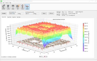
The plots for surface, touch, and step voltages from the modelling software (including with rods) are shown in the Appendix.

Figure 1. 20m×20m 16-mesh grid model

Figure-1-20m×20m-16-mesh-grid-model

Figure 2. Multilayer winter soil model with the grid buried at 0.45 m

Figure-2-Multilayer-winter-soil-model.

Conclusions and Recommendations

For an earthing design to be accurate it is important to consider the soil resistivity conditions for all seasons – this is covered in IEEE Std. 81 [2]. For locations where the soil surface layers can freeze during winter, the soil resistivity will significantly increase affecting the earthing and giving rise to higher touch voltages during fault conditions during winter or early spring. Therefore, an earthing designer must consider the worst-case soil resistivity during these times and a conservative soil model must be utilized.

We recommend the following:

  1. Take soil resistivity measurements during summer and winter conditions.
  2. Include the frozen top-soil layers in your soil resistivity model.
  3. Where the soils can be frozen during winter, utilize vertical rods for your designs to significantly reduce touch voltages.

References

[1]        IEEE Std 80-2013, IEEE Guide for Safety in AC Substation Grounding.

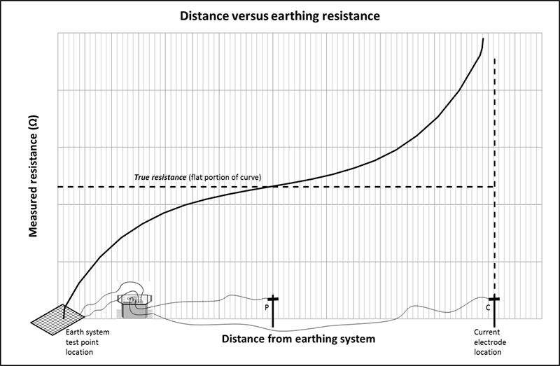
[2]        IEEE Std 81-2012, IEEE Guide for Measuring Earth Resistivity, Ground Impedance, and Earth Surface Potentials of a Grounding System.

[3]        SafeGrid Earthing Software, V5.1.

Appendix – Modelling results

Surface Voltages

Figure 3. 3D surface voltages for summer soil model

Figure 3 surface Voltage of the uniform soi - Earth Grid Design for Frozen Soils

Figure 4. Line profile plot of surface voltages for all soil models

Figure 4 Surface Voltages of the three soil  - Earth Grid Design for Frozen Soils

Figure 5. Line profile plot of surface voltages for all soil models – including rods

Figure 5 Surface voltages of a grid with rods. - Earth Grid Design for Frozen Soils

Touch Voltages

Figure 6. 3D touch voltages for summer soil model

Figure 6 Touch voltage of the uniform soil m - Earth Grid Design for Frozen Soils

Figure 7. Line profile plot of touch voltages for all soil models

Figure 7 Touch voltages of the three profiles - Earth Grid Design for Frozen Soils

Figure 8. Line profile plot of touch voltages for all soil models – including rods

Figure 8 Touch voltages of the grid with rods - Earth Grid Design for Frozen Soils

Step Voltage

Figure 9. 3D touch voltages for summer soil model

Figure 9 Step voltage of the uniform soil mo - Earth Grid Design for Frozen Soils

Figure 10. Line profile plot of step voltages for all soil models

Figure 10 Step voltages of the three profiles - Earth Grid Design for Frozen Soils

Figure 11. Line profile plot of step voltages for all soil models – including rods

Figure 11 Step voltages of the grid with rods - Earth Grid Design for Frozen Soils

Related Articles:

elek article header ed fundamentals sm - Earth Grid Design for Frozen Soils

Fundamentals of Earthing Design

This tutorial introduces key concepts used in the design of substation earthing/grounding systems. Important terminology is discussed including Grid Potential Rise, touch and step voltages and current distribution.

Read It Now
Ligthning Protection - Earth Grid Design for Frozen Soils

Lightning Protection Tutorial

The Lightning Protection Module in SafeGridTM allows the user to overlay lightning protection systems (LPS) such as lightning masts and earth wires over a PDF schematic.

Read It Now

SafeGrid Earthing Software

Easily design safe earthing systems in compliance with Standards.

Try For Free

Print this article:

Share on print
Print

SafeGrid Earthing Software

SafeGrid Earthing Software

Easily design safe earthing systems in compliance with Standards.

Try For Free

As used by:

For information or to speak with our helpful advisors

GET IN TOUCH

GET IN TOUCH

Electrotechnik-Footer

Electrical Power Systems Design & Analysis Software

FOLLOW US

social-fb
social-yt
social-li

SOFTWARE

  • Cable Pro Web
  • Protection Coordination
  • SafeGrid Earthing
  • Cable High Voltage
  • Cable Pulling
  • Line Rate
  • Power Bundle
Menu
  • Cable Pro Web
  • Protection Coordination
  • SafeGrid Earthing
  • Cable High Voltage
  • Cable Pulling
  • Line Rate
  • Power Bundle

RESOURCES & SUPPORT

  • Software Tutorials
  • Technical Publications
  • Training and Certification
  • Customer Licence Portal
Menu
  • Software Tutorials
  • Technical Publications
  • Training and Certification
  • Customer Licence Portal

CONTACT US

Email:
enquiry@elek.com.au

Need Help?
Lodge a Support Ticket

Phone:
1300 093 795
International:
+61 (0)2 8231 6673

FREE TECHNICAL NEWS

© 2022 All Rights Reserved    Privacy Policy Quality Policy Terms of Use

Schedule a Demo for Cable High Voltage

Look No Further. Get Started Today

  • This field is for validation purposes and should be left unchanged.
Schedule a Demo for SafeGrid Earthing

Look No Further. Get Started Today

  • This field is for validation purposes and should be left unchanged.
SafeGrid Earthing Free Trial
  • Fill out your details below to begin your trial. Once your information has been submitted you'll be able to download the software.

  • This field is for validation purposes and should be left unchanged.
Cable High Voltage Free Trial
  • Fill out your details below to begin your trial. Once your information has been submitted you'll be able to download the software.

  • This field is for validation purposes and should be left unchanged.
SafeGrid Earthing 14 day Free Trial

Fill out your details below to begin your trial. Once your information has been submitted you’ll be able to download the software.

  • Fill out your details below to begin your trial. Once your information has been submitted you'll be able to download the software.

  • This field is for validation purposes and should be left unchanged.

CLOSE

Cable High Voltage 14 day Free Trial

Fill out your details below to begin your trial. Once your information has been submitted you’ll be able to download the software.

  • Fill out your details below to begin your trial. Once your information has been submitted you'll be able to download the software.

  • This field is for validation purposes and should be left unchanged.

CLOSE

  • We strive for 100% customer satisfaction. If we fell short, please tell us more so we can address your concerns.

  • This field is for validation purposes and should be left unchanged.

If you do not wish to address your concerns here and prefer to post a review, click here.

Cable Pro (PC) Free Trial

Fill out your details below to begin your trial. Once your information has been submitted you’ll be able to download the software.

  • Fill out your details below to begin your trial. Once your information has been submitted you'll be able to download the software.

  • This field is for validation purposes and should be left unchanged.

CLOSE