Call Us: 1300 093 795
Email Us: enquiry@elek.com.au

  • Login Cable Pro
Menu
  • Login Cable Pro
Electrotechnik
  • Software
    • Cable Pro Web (AU)
    • Cable Pro Web (UK)
    • Protection Coordination
    • SafeGrid Earthing
    • Cable High Voltage
    • Cable Pulling
    • Bare Conductor Ratings
    • Power Bundle
  • Resources
    • Article Categories
      • Low Voltage Design
      • Earthing Design
      • High Voltage Cable Design
      • Electrical Software
      • Arc Flash Studies
    • Tutorials
    • Free Calculators
      • Cable Sizing AS3008
      • Cable Sizing BS7671
      • Voltage Drop
      • Arc Flash
      • Earth Cable Sizing
      • Fault Loop Impedance
      • Earth Grid Resistance
      • Earth Grid Conductor Sizing
      • Earthing Rods Resistance
      • Lightning Protection Design
      • Relay Tripping Time
      • Equivalent Thermal Resistance
    • Courses
      • SafeGrid Earthing Software Course
    • Technical Publications
    • Training and Certification
  • Support
    • Support Overview
    • Help Portal
  • About
    • About Us
    • Contact Us
    • Services
    • Careers
    • Reseller & Partner Program
  • Login
    • Cable Pro Web Login
    • Training Courses Login
    • Customer Licence Portal
  • TRY FOR FREE
  • SCHEDULE A DEMO
  • TRY FOR FREE
  • SCHEDULE A DEMO
  • TRY FOR FREE
Menu
  • Software
    • Cable Pro Web (AU)
    • Cable Pro Web (UK)
    • Protection Coordination
    • SafeGrid Earthing
    • Cable High Voltage
    • Cable Pulling
    • Bare Conductor Ratings
    • Power Bundle
  • Resources
    • Article Categories
      • Low Voltage Design
      • Earthing Design
      • High Voltage Cable Design
      • Electrical Software
      • Arc Flash Studies
    • Tutorials
    • Free Calculators
      • Cable Sizing AS3008
      • Cable Sizing BS7671
      • Voltage Drop
      • Arc Flash
      • Earth Cable Sizing
      • Fault Loop Impedance
      • Earth Grid Resistance
      • Earth Grid Conductor Sizing
      • Earthing Rods Resistance
      • Lightning Protection Design
      • Relay Tripping Time
      • Equivalent Thermal Resistance
    • Courses
      • SafeGrid Earthing Software Course
    • Technical Publications
    • Training and Certification
  • Support
    • Support Overview
    • Help Portal
  • About
    • About Us
    • Contact Us
    • Services
    • Careers
    • Reseller & Partner Program
  • Login
    • Cable Pro Web Login
    • Training Courses Login
    • Customer Licence Portal
  • TRY FOR FREE
  • SCHEDULE A DEMO
  • TRY FOR FREE
  • SCHEDULE A DEMO
  • TRY FOR FREE
Home / Articles / High Voltage Design

Current Rating of Cables in Ventilated Tunnels

IEC method for multiple circuits explained with example calculations
1653368710952 1170x585 - Current Rating of Cables in Ventilated Tunnels

Overview

This paper describes the method and has examples for calculating the steady-state current rating of cables installed in ventilated tunnels. In the examples, multiple cable circuits installed in a ventilated tunnel are simulated and the effects of varying parameters such as depth of tunnel axis, length of tunnel and air velocity inside the tunnel on the cable current ratings are shown.

The calculations were performed using ELEK Cable High Voltage™ Software.

IEC calculation method for ventilated tunnels

The Standard IEC 60287-2-3 [1] details a methodology to calculate the steady-state current rating for cables of all voltages installed in tunnels with natural or forced ventilation. The method is based on the calculation of the temperature of the cable surface, the air in the tunnel and the tunnel wall as a function of the heat generated by the cables. Consideration of longitudinal temperature gradients is involved as the moving air inside the tunnel (assumed to be either laminar or turbulent depending on the air velocity) removes heat from the cables. Longitudinal heat transfer within the cables and the surroundings of the tunnel on the other hand is assumed to be negligible and heat generated by a cable is assumed to be constant along its length.

The method is applicable to any type of cable and for multiple circuits. Where multiple circuits are involved, their characteristics are assumed to be identical. Only steady state conditions are considered, where the inlet air temperature and the cable loading are constant for a sufficient time for steady temperatures to be achieved.

The current rating of cables inside a tunnel depends on the air temperature. The longitudinal air movement in the tunnel dissipates heat from the cable surface along the tunnel axis. This creates an increase in air temperature along the tunnel axis as we move away from the inlet. The following heat transfer mechanisms are considered:

  • Radial conduction within the cable.
  • Radiation from the cable surface to the tunnel wall.
  • Convection from the cable surface to the air inside the tunnel.
  • Convection from the air inside the tunnel to the tunnel wall.
  • Longitudinal heat transfer by convection resulting from air flow (laminar or turbulent depending on velocity).

A thermal network representing slices of the tunnel cross section, is considered and the slices are linked by the longitudinal heat transfer of the air flow along the tunnel. A delta-star transformation is applied on ever slice to derive a thermal network with one thermal resistance each between the star point and the cable surface, the tunnel wall, and the ventilating air respectively. This results in a fictitious increase of the ambient temperature to account for the ventilation. The equivalent thermal resistance of the cable surrounding is calculated (iteratively) and used in the steady state calculations to obtain the current rating.

Example calculations

Cable model

The cable model considered in this study is a 132 kV 1000 mm2single core cable as shown in Figure 1. The cable has an outer diameter of 99.3 mm.

Figure 1. Cross-section of the cable model (not to scale)

Tunnel parameters

The tunnel considered in this study has the following parameters.

Table 1. Tunnel parameters
Parameter Value Unit
Native soil thermal resistivity 1.852 K.m/W
Tunnel shape Circular -
Tunnel outer diameter 3.2 m
Tunnel inner diameter 3 m
Tunnel wall thermal resistivity 1 K.m/W
Temperature at the ground level 25 oC
Temperature at tunnel inlet 40 oC

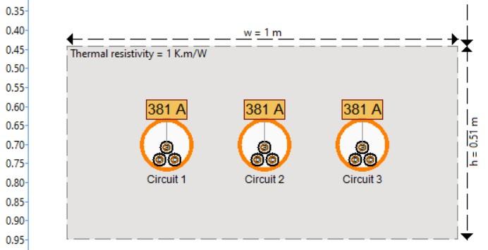
Arrangement of the circuits

The cables circuits are arranged in trefoil and spaced vertically along the inner edges of the tunnel wall as shown in Figure 2. This image was taken from ELEK Cable HV™ Software.

Figure 2. Tunnel simulation model with 5 x 132 kV cable circuits

Variation of current rating with tunnel length

The length of tunnel is varied and its impact on the current rating was examined. The different tunnel lengths considered were 500 m, 1 km, 5km and 10 km. The tunnel axis is at 2m below the ground surface and the air velocity inside the tunnel is 2 m/s.

The results shown in  Figure 3 indicates with increasing tunnel length there is a non-linear reduction in cable current rating. The total variation in cable current rating between the 500 m tunnel and the 10 km tunnel is 44%.

Figure 3. Variation of current rating with tunnel length

Variation of current rating with air velocity

The air velocity inside the tunnel which is assumed to be constant along the length of the tunnel was varied between 0.5 m/s and 5 m/s. As air velocity increases the longitudinal heat transfer along the tunnel length increases. This tends to cool the cables down which in-turn increases their current carrying capacity. The fixed tunnel parameters were length 1000 m and tunnel axis 2 m below the ground surface.

Table 2 shows that as air velocity increases the temperatures inside the tunnel decrease which increases cable current rating. Figure 4 shows how cable surface temperature (correlated with cable current rating) varies with change in air velocity inside a tunnel. The percentage increase of the current rating between a tunnel air velocity of 0.5 m/s and 5 m/s was 45%.

Table 2: Parameters of the study at the tunnel outlet for varying wind speeds
Air velocity inside the tunnel (m/s) Tunnel air temperature,

θat (oc)

Tunnel wall temperature,

θt (oc)

Cable surface temperature,

θs (oc)

Current rating of cables (A)
0.5 83.069 81.679 85.972 497.8
1 80.841 80.360 84.777 569.47
2 77.436 77.618 82.406 686.23
3 74.658 75.056 80.179 776.08
5 70.430 70.941 76.492 907.74
Figure 4. Temperature of cable surface for different air velocity along the length of tunnel

Variation of current rating with depth of tunnel axis

The depth of the tunnel axis was changed and its impact on the current rating investigated. The tunnel axis depth was varied to 2 m, 4 m and 5 m. The length of the tunnel was fixed at 1000m with constant air velocity of 2 m/s. Table 3 shows for deeper tunnel depth the cable current rating was reduced but not by too much. The percentage reduction of the current rating between a tunnel with only 2 m depth compared with 5 m depth was under 5 %.

Table 3. Variation of tunnel depth effects on cable current rating
Depth of tunnel axis (m) Tunnel air temperature,

θat (oc)

Tunnel wall temperature,

θt (oc)

Cable surface temperature,

θs (oc)

Current rating of cables (A)
2 77.436 77.618 82.406 686.23
4 78.217 79.09 83.073 657.77
5 78.360 79.360 83.196 657.77

Conclusion

A computer software implementation of the IEC standards for calculating cable current ratings in ventilated tunnels has allowed this common installation method to be modelled. Multiple cable circuits installed inside the same tunnel can be modelled simultaneously.

A parametric study involving varying certain tunnel model parameters has revealed whether their effects on the cable current rating results are significant or not so. For example, the overall length of the tunnel and the air velocity inside of the tunnel both have significant impact on cable current ratings whilst tunnel depth does not.

References

  1. IEC 60287-2-3 Edition 1.0 2017-04 Electric cables – Calculation of the current rating – Part 2-3: Thermal resistance – Cables installed in ventilated tunnels

Related Articles:

elek articles hv cymcap compare - Current Rating of Cables in Ventilated Tunnels

Comparison of CYMCAP with Cable HV

We have benchmarked our Cable HV Software current rating results for 110 kV cables against the well-known software CYMCAP. We have shown the results are virtually identical (under 1.5 % difference).

Read It Now
elek articles hv power cables - Current Rating of Cables in Ventilated Tunnels

High Voltage Power Cable Current Ratings

Submarine power cables are not new and have been around for more than a century. In early times, they were used to supply lighthouses and ships.

Read It Now
Cable HV Software

Custom cable ratings for a wide range of installation conditions.

Try For Free

Print this article:

Share on print
Print
Cable HV Software
Cable HV Software

Custom cable ratings for a wide range of installation conditions.

Try For Free

As used by:

For information or to speak with our helpful advisors

GET IN TOUCH

GET IN TOUCH

Electrotechnik-Footer

Electrical Power Systems Design & Analysis Software

FOLLOW US

social-fb
social-yt
social-li

SOFTWARE

  • Cable Pro Web
  • Protection Coordination
  • SafeGrid Earthing
  • Cable High Voltage
  • Cable Pulling
  • Line Rate
  • Power Bundle
Menu
  • Cable Pro Web
  • Protection Coordination
  • SafeGrid Earthing
  • Cable High Voltage
  • Cable Pulling
  • Line Rate
  • Power Bundle

RESOURCES & SUPPORT

  • Software Tutorials
  • Technical Publications
  • Training and Certification
  • Customer Licence Portal
Menu
  • Software Tutorials
  • Technical Publications
  • Training and Certification
  • Customer Licence Portal

CONTACT US

Email:
enquiry@elek.com.au

Need Help?
Lodge a Support Ticket

Phone:
1300 093 795
International:
+61 (0)2 8231 6673

FREE TECHNICAL NEWS

© 2022 All Rights Reserved    Privacy Policy Quality Policy Terms of Use

SafeGrid Earthing 14 day Free Trial

Fill out your details below to begin your trial. Once your information has been submitted you’ll be able to download the software.

  • Fill out your details below to begin your trial. Once your information has been submitted you'll be able to download the software.

  • This field is for validation purposes and should be left unchanged.

CLOSE

Schedule a Demo for Cable High Voltage

Look No Further. Get Started Today

  • This field is for validation purposes and should be left unchanged.
Schedule a Demo for SafeGrid Earthing

Look No Further. Get Started Today

  • This field is for validation purposes and should be left unchanged.
SafeGrid Earthing Free Trial
  • Fill out your details below to begin your trial. Once your information has been submitted you'll be able to download the software.

  • This field is for validation purposes and should be left unchanged.
Cable High Voltage Free Trial
  • Fill out your details below to begin your trial. Once your information has been submitted you'll be able to download the software.

  • This field is for validation purposes and should be left unchanged.
Cable High Voltage 14 day Free Trial

Fill out your details below to begin your trial. Once your information has been submitted you’ll be able to download the software.

  • Fill out your details below to begin your trial. Once your information has been submitted you'll be able to download the software.

  • This field is for validation purposes and should be left unchanged.

CLOSE

  • We strive for 100% customer satisfaction. If we fell short, please tell us more so we can address your concerns.

  • This field is for validation purposes and should be left unchanged.

If you do not wish to address your concerns here and prefer to post a review, click here.

Cable Pro (PC) Free Trial

Fill out your details below to begin your trial. Once your information has been submitted you’ll be able to download the software.

  • Fill out your details below to begin your trial. Once your information has been submitted you'll be able to download the software.

  • This field is for validation purposes and should be left unchanged.

CLOSE